Firstly, that wiring diagram doesn’t include using the triggers at all, so you don’t need to worry about the resistors; just leave the potentiometers on the board and remove the trigger itself. All you have to do is remap the button in the options of the game (for me, it’s LB = hard kick/roundhouse/whatever you wanna call it).
Secondly, here is a wealth of knowledge regarding solding to the actual board.
Thirdly, get yourself some quick disconnects (for Sanwa, for Happ) for all the little tabs on the buttons themselves, and a crimper. Instead of doing allllll that soldering, just make a daisy chain of wires for the common ground. That’s what I did with mine and it worked very well. I can post a picture of what mine looks like, but it’s very easy to understand: take the bare ends of two wires, twist together, put the twisted-together wires into the quick disconnect, crimp, stick the Q.D. on the tab of the button, done.
You will need to scrape the trace to reveal the copper underneath. This is the line leading up to where the pad used to be. These are obnoxiously small on the Mad Catz pads. I used a small flathead screwdriver, scraped the length of my stripped wire and was able to solder it on. Once I knew it took I hot glued in excess to keep it from budging. It’s not fun but it’s doable if you don’t want to buy another controller.
Sorry if this sound stupid, but do you mean if i don’t want to use the LT+RT triggers i don’t have to desolder the potentiometers(?) from the board and all need to do is remove the trigger itself (the plastic) and i am set without doing anything else?
That was the video tutorial i was talking about, it’s extremely helpful i will watch it again in case i missed something.
As for the quick disconnects it’s seems the easiest way but is there anything wrong in the method i described?
I am asking this in case i don’t manage to find any, since i leave in Europe and i don’t know for example if modchipman ships worldwide.
If you can find the time and post a pic of your quick disconnects please do it, just to have an idea of what looks like.
sorry for this super newbie question ive been using search function extensively…i think i know the answer but imma double check with you guys…its my first custom stick/experience with wiring/soldering
**i got the happ controls and cherry microswitches…i have a ps1 DS PCb…
can the common ground wire for all the buttons be placed at any common ground spot on the PCB or is there an optimal spot?
and also for the joystick common ground wire:
can i place them in a different common ground spot or do i connect it to the same common ground spot with the buttons?**
sorry for the newbie question i just have to make sure…
PSN: So-VIET for SFIV/T5DRO…im not a newb on there =P
Any common ground spot is fine, that’s why they’re common… You can hook the joystick to the same spot as the buttons, or a different one, whichever is more convenient.
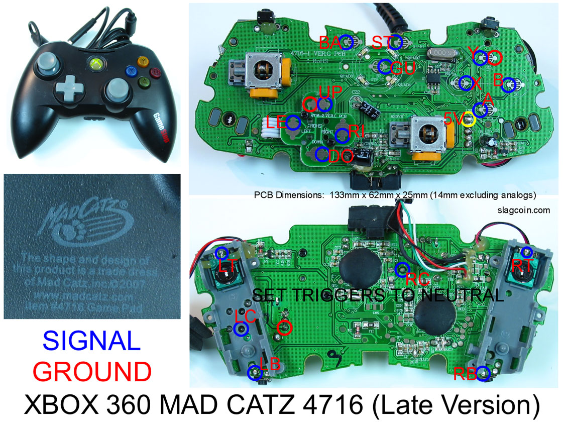
I have this pad and it says set triggers to neutral. I heard this involves diodes/resistors, which would I need specifically? and where would they go on this PCB?
Neutral means don’t do anything with them, so you don’t need to do anything with them unless you plan on using them as usable buttons on your joystick.
If you are doing a dual system stick then you need to use an inverter chip and a resistor. Otherwise the transistor and resistors will do you fine. Here is the thread with all the information… http://forums.shoryuken.com/showthread.php?t=169203
Does anyone hot glue the wire down an inch or so from the actual soldering point? I was thinking of doing this from here on out instead of putting glue on the points. A couple of days back I was trying to remove glue from a hacked pad and ripped off a couple of the copper pads. It made me reconsider putting glue on them at all.
I was wondering: what about using optocouplers instead of an inverter chip if you want to dual mod your stick ? 2 octocouplers aren’t going to break the bank, plus are easier to connect than a DIL chip.
i’m still trying to get help with this and i’m getting desperate, can anyone else help AT ALL?
anyone who knows the late wired xbox 360 controller and can provide an alternate place to solder OTHER THAN TP cause I can’t really afford another control atm. everything else is perfectly fine, just right d-pad which is shit cause its essential.
Once you pop the plastic caps off the analog sticks are you guys Dremel/Grinding them down? I was also thinking of filling them with hot glue. Any thoughts?
what i did was take the banana bit off but make sure the pots were in the neutral position - as the bit that moves is in when the triggers are unpressed - and then superglue them in there so it cant move. that way you keep space down with the least work
Just completed my first padhack, of a common ground MS wireless 360 controller. Pretty painless, other than the tiny contacts for the dpad. I’ve tested it all out. No hot glue, so hopefully all the zip ties and electrical tape help keep the wires from moving too much. I’m pretty happy with the results.
Hey so first of all bear with me as I’m learning =P
So, I have a wired 360 controller apart and ready to be soldered, the thing is, I had it plugged in and was testing the buttons out with a piece of wire, making the connections to see if it worked, which it did when I connected the two contacts for the ‘A’ button or the two contacts for the ‘B’ button. But my concern is when you connect the signal from the ‘a’ button to the common of another button, it doesn’t register on the xbox, now I understand your supposed to ‘daisy chain’ all the grounds together, so I’m wondering if there is a specific place the end of your daisy chain should go.
With that picture that was posted a couple pages back it showed the end of the chain going to the common of the ‘select’ button, but if i make a connection between the ‘a’ button and the select button nothing happens, and yes the controller still works because ive reassembled it and its fine, nothing shorted yet haha
Anyways I was debating just running a separate ground for each button but if someone could share some insight I would much appreciate.
 You can hook the joystick to the same spot as the buttons, or a different one, whichever is more convenient.