Here’s how I’m going to wire it:
http://i652.photobucket.com/albums/uu244/Gizzmo0815/JoytechNeoSE4716VerBWithWiring.jpg?t=1239834902
Here’s how I’m going to wire it:
http://i652.photobucket.com/albums/uu244/Gizzmo0815/JoytechNeoSE4716VerBWithWiring.jpg?t=1239834902
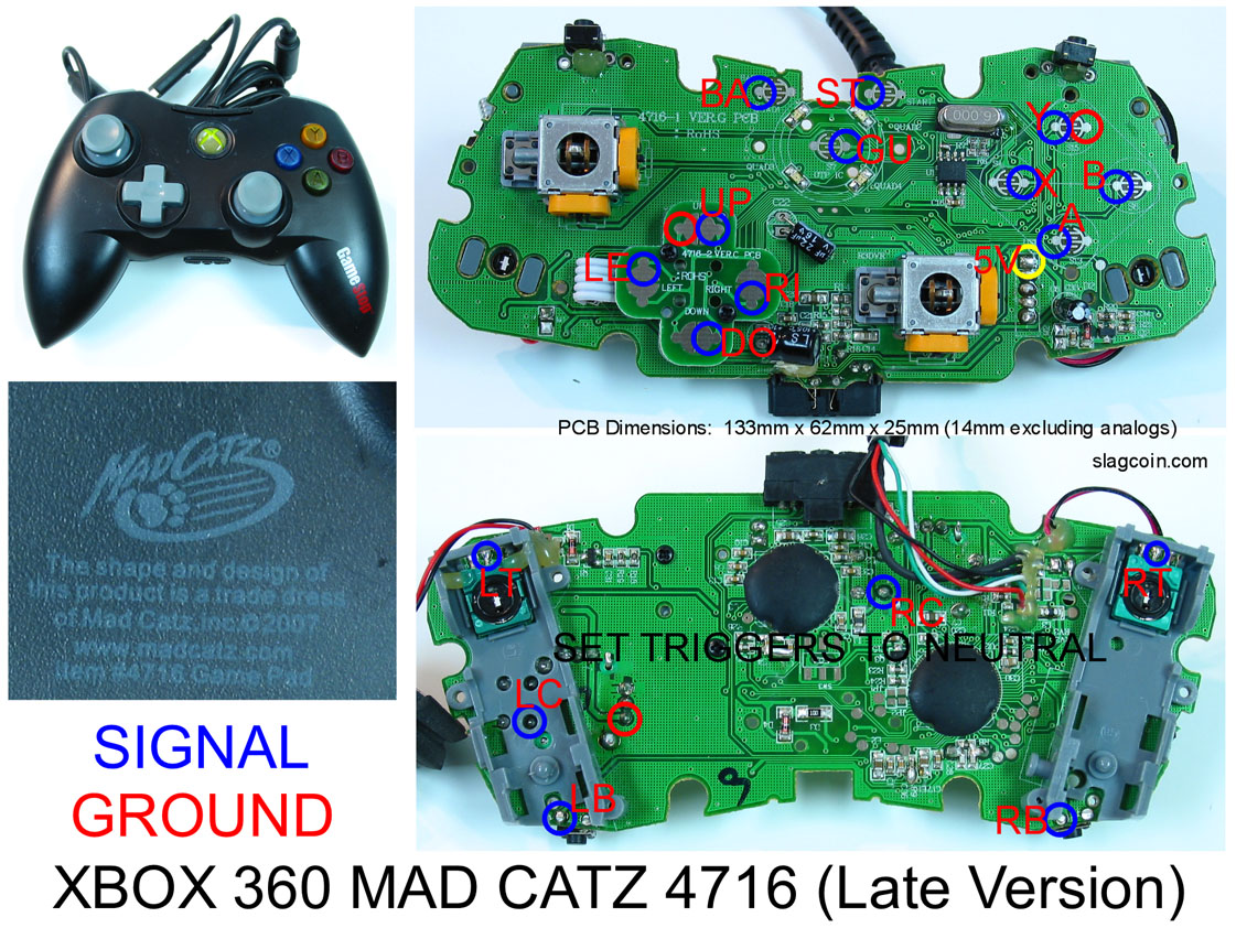
Everything looks good, except your LT/RT. The LT and RT signals are the middle post, that you have marked yellow, and they are grounded when not pressed, and high when pressed. In order to use them with a common ground, you’ll need to remove the pots and use two resistors and a transistor per trigger. There’s a thread on hacking the madcatz triggers specifically, let me find it and I’ll edit this.
(edit)
Here’s a pic of how to wire the triggers:
http://picasaweb.google.com/wliu0912/PrehackedPads?feat=directlink#5313446559450665170
And the thread about it:
http://forums.shoryuken.com/showthread.php?t=169203
Your ground and high are colored right, and the yellow is the wiper.
how come your solder is white?
I believe that is Elmer’s Glue used in place of Hot Glue but I have been wrong before.
well now i’m confused.
that thread says this one is the easier to hack pad.
(refers to it as easier/older version)
but this is the one i have and slagcoin refers to it as the late model.
which is it?
edit:
never mind - turns out the model i have is the late 2007 rev-g. the one they’re refering to in the madcatz thread is actually the NEWER than LATE model. guess i lucked out.
Milkham and mjb: yeah its just the normal glue.
can nobody help at all? just an idea of where the trace leads (preferrably further away than the place i’ve fucked up. thanks
http://img.photobucket.com/albums/v231/Chris_Andon/pcb3.jpg
i’ve scraped away to reveal copper at the little hole here. i think this is the trace, but i’d really like some advice before i go fucking it up again. thanks for helping
I don’t understand why the transistor/resistor fix is necessary if I intend to leave the POTS in place glued into the same position they’d be in if UN-pressed. I’m not saying you’re wrong, I just don’t understand the electronics behind why it doesn’t work, if I keep them there, wire the ground to the ground on the button, and the wiper to the signal on the button.
The thing is, all of the digital buttons activate by being shorted to ground, but the triggers activate on this controller by going from ground to high, 3.3v I think offhand. They’re normally grounded, so running a wire from ground to button to wiper would do nothing except signal that the trigger is unpressed when you press it, which it will already be unpressed, for a net result of nothing.
You use the transistor and resistors to build an inverter, so that when the transistor is grounded, it pulls the wiper high, and signals the trigger as activated. Unfortunately, you can’t use that setup while the pot is still attached.
I want to connect the JLF + 6 Sanwa OBSF - 30 buttons to a 360 common ground PCB
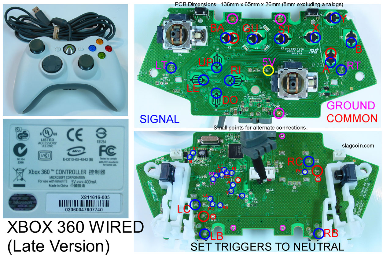
Specifically i have the official wired 360 controller
First of all do i need anything else to have besides the ones listed below? (correct me if i need anything else please)
360 wired common ground PCB
Sanwa JLF
http://www.arcadeshop.de/Joysticks-JLF-TP-8YT-Sanwa_627.html
http://www.arcadeshop.de/Control-Parts-Stickharness-JLF-H_640.html
6 Sanwa OBSF - 30 buttons (plus 2 button plugs)
Soldering iron + soldering wire
Desoldering tool
Wire harness for the buttons
A sharp knife or just a screwdriver to “expose” the contants on the pcb
Now, i watched a video on youtube that help me a lot but i still have some questions
I don’t need the LT+RT triggers, can i just leave them there in the pcb or i will have problems?
Can someone please post a diagram on how to connect the buttons + jlf to my pcb? As i said above it’s the official 360 wired controller and it’s common ground.
Oh, and about the back + start + guide buttons i plan to use the the three of the four small buttons in the Mayflash stick, because that’s the stick i am trying to mod.
EDIT: Nevermind, found pics of what I needed.
1.) You can just leave the potentiometers on the board if you don’t plan on using the triggers without any problems.
2.) I can draw something up sort of like the one I did for the non-common ground wired 360 pad on the last page. It’s not really all that hard, don’t worry. The up/down/left/right soldering will depend on the orientation of the joystick with its red/green/orange/yellow shenanigans.
Thanks for the reply, at least i don’t have to worry for the triggers anymore.
A diagram would be extremely helpful, since this will be my first time soldering anything.
Also can you (or anyone else) please confirm that i don’t need anything more other than the things i posted above? I just want to have everything ready.
You list is pretty good. By wiring harness for the buttons do you mean the quick disconnects? A terminal strip would be a good idea; wish I had one for my first joystick. And get yourself an xacto knife or something like that, not just a sharp knife or a screwdriver. An xacto knife is very useful and will come in handy if you ever need to cut a trace (I had to and it worked pretty well).
I’ll be making that diagram on my lunch break (~12 CDT).
Thanks to the information in this forum i was able to successfully hack a madcatz late version pad last night and install it into a C&L Controls Championship Joystick (old school SNES stick) with almost no prior electrical work experience. (not since middle school, 20 years ago)
Thanks to all who contribute here! (and to whoever runs slagcoin!) One note however, the useful information is scattered all over the place, it would be cool if the original poster took some time to consolidate the information, or if we could get it onto a wiki…
-Xaanix
so some how my madcatz late version, the trace for the guide button got removed how may i fix this? Is there alternative solder point?
this is the controller

You can solder directly to the trace if you can scrape enough of the green stuff off.
edit: I just reread that: the whole TRACE is gone, or do you mean the little spot where you would traditionally solder a wire on to?
Just the little spot, i can’t get the wire to stick to the side of the spot, or it just touch the trace to the left.
Pictures would help a lot here 
Ok, this diagram took a little longer than I expected, but it works. Some of the lines are hard to see, I appologize. The following link will open a window for “how to wire a 360 common ground controller to 6 buttons without the triggers:”
The orientation of the joystick is key, and I illustrated the diagram how it’s supposed to sit: with the harness in the lower-right corner. I used the JLF FAQ from LizardLick’s website to determine which color you should be soldering to which direction. Ask away if you have any questions.
I got all my parts today for my stick (happ) I plan on building the case this weekend. The wood working aspect of the job doesn’t bother me in the least, but the wiring part does. I’m going to be using my wired xbox 360 controller, but I’m not sure whether or not the pcb inside is common ground. Does anyone have any tips to find if it is or not? The controller is about 2 years old, and the model # sticker on the bottom that covers some screws fell off… lol.
Thanks guys, I will most likely have more questions as I progress through this project, so hopefully I can get some help so I don’t blow my xbox up
Thank you, that was really helpful.
I plan to use just a 22 awg one color wire in a cylinder and cut the number and the length of wires i need myself. I think this wire is called “solid” as i read in slagcoin.
So, i take the black wire from the Stickharness JLF-H which is the common wire and i pass it to all the buttons and finally to the common ground in the 360 pcb which is the right contact of the back button.
As for the signals i just have to connect the correct buttons to the correct contacts as shown in your diagram, i take that in Stickharness JLF-H the black is common, the red is up, the orange is down, the green is left and the yellow is right.
Now, i know that i have to “expose” the contacts for the signals with a xacto knife, i guess i have to do the same for the one common contact. I am asking this just to be sure.
My three main concerns (if i am not saying anything wrong until now) is first how to pass and solder the common wire of the JLF-H to all the buttons and finally to the common contact.
I am thinking of doing it like this, first solder the black wire from the JLF-H to the first button microswitch.
Then cut a new wire, and solder the new wire in to the black wire of the JLF-H that it is soldered in to the button microswitch. Then connect the other end of that wire to the second button microswitch.
Repeat this process for all the buttons and finally connect the wire from the last button microswitch to the common contact in the pcb.
Second do i have to “expose” with the xacto knife the directional signal contacts “dots” first before soldering the wires into them as i will do with the button contacts or i will just solder the wires into the “dots” without first “expose” them. Exactly the same question for the LB and RB contacts.
Last, i don’t know much about resistors, can you point me to a link for the correct one i need? Also although i know how to remove the triggers from the board i don’t know on where and how to solder the resistor in to the PCB.
Sorry for the long message but as i said i have zero experience with this stuff and just recently i start reading about them.
Also please excuse any grammatical/spelling errors.