What about if the triggers alone require a separate ground? I’m trying to make a Wavebird or Wiimote compatible with my CG Saturn pad. Can I just split the CG wire from the Saturn pad and solder it to the trigger CG AND the main CG?
You are not! Non-common ground boards need to have everything properly grounded with no daisy chaining, like my wee drawing up there. There are a couple of buttons that use the same ground that you can do daisy chaining on, but not as much chaining as you can have with a common ground where you only need to solder one ground wire to the PCB that works with everything.
Anyone know if there are alternative solder points for the MS Wireless CG pad? I managed to rip off every direction but up =(
great, thanks a ton
when using the 360 wired PCB, is it possible to still use the headset port if I place it well?!
They exist for the wired “late” model, but I think you might be out of luck for the wireless.
Yup. The way I’m setting mine up is to mount the PCB on the south wall with a little hole for the port to stick out of. You can desolder the points where the port is attached to the PCB, but I dunno which of the contacts you’re supposed to use and wouldn’t recommend it.
you dont have a diagram of the fixed version without mistakes? also for rb and lb can i use those small metal points on the front of the pcb? if so whats the ground of those?
I think i want to buy a common madcatz pcb but no one on ebay seems to sell the common one that ships to canada
http://cgi.ebay.ca/Madcatz-Wired-Microsoft-XBOX-360-White-Controller-NEW_W0QQitemZ390041784647QQcmdZViewItemQQptZVideo_Games_Accessories?hash=item390041784647&_trksid=p3286.c0.m14&_trkparms=72%3A1215|66%3A2|65%3A12|39%3A1|240%3A1318
i dont think these are the common ones and thats all ebay has
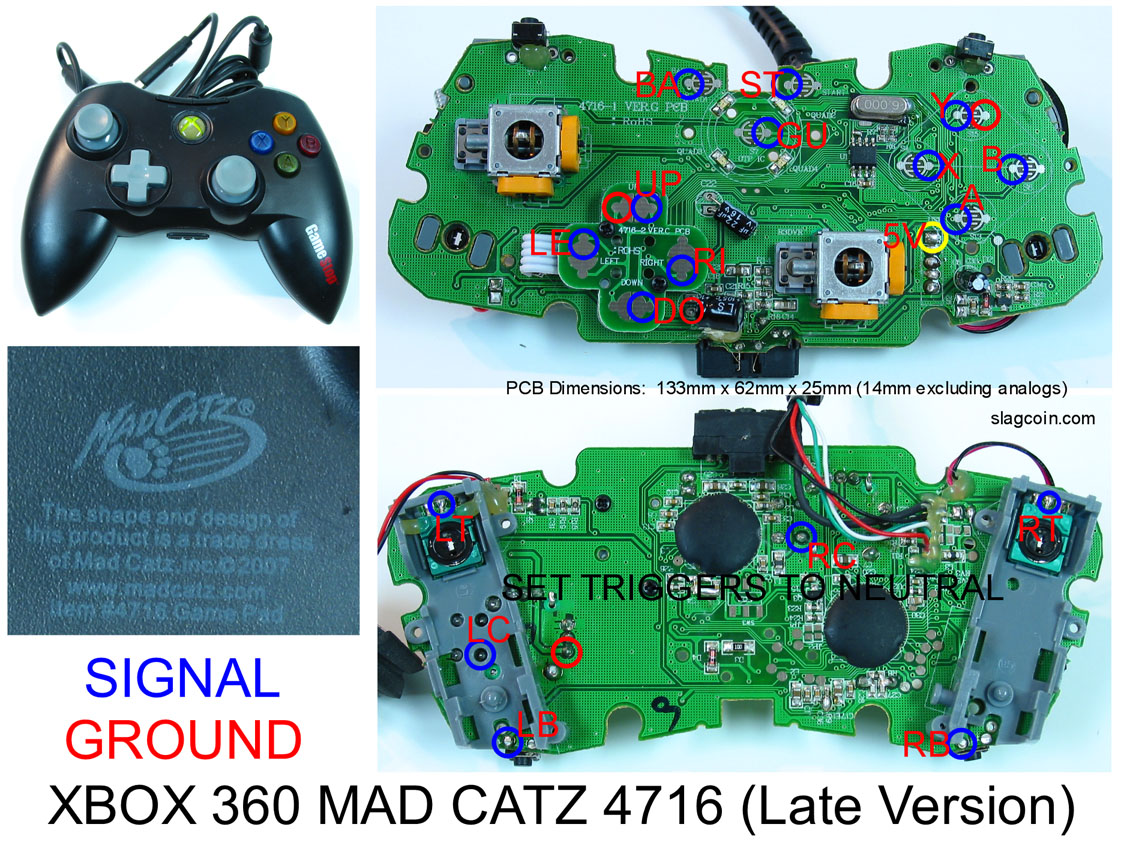
I have this exact PCB (it is DEFINITELY the revision shown in this pic). I keep reading that for this model you need resistors in-line, but for this other revision you need an inverter chip, and then there’s a still older revision that needs something else.
I’ve read Toodles’ Instructables guide forward and backward, ten pages in the http://forums.shoryuken.com/showthread.php?t=169203 thread and still more pages here. I think the whole experience has been counter-productive so far, as I have even less of a clue than when I started.
I want to use the triggers. I have removed the potentiometers for them so nothing is left except their solder points (aka “copper pads” in the instructables guide, though I haven’t removed the solder from them yet). I have resistors in front of me. I also removed the raised d-pad so I have access to the LT test point on the front.
When I plug the controller in to my computer, LT and RT are neutral.
When I connect the LT test point to ground, LT and RT (buttons 11 and 12 in ‘Game Controllers’ screen, xp 32-bit with XBCD drivers installed) both light up at the same time.
- Do I need to remove the solder from those potentiometer’s copper pads like in the picture? If so, why?
- Where do I use the resistor? Between the test point and a ground? Somewhere on the copper pads the potentiometer used?
I’m figuring this has been explained in detail on one page somewhere, but I’ve yet to find that page. All I’ve found are smatterings of info here and there. Sorry if this has blatantly been addressed already, but I’ve RTFM’d MAO already and I’m done wasting time. I can post pics/videos if necessary.
As always, thanks for all the help. It is VERY VERY VERY appreciated.
EDIT: One of the posts on the last page looks promising.
“Mad Catz 4716 2007 model: 10k resistor between signal (wiper or middle pad) and high (5v, 3v, Vcc, whatever). The arcade button then takes a line from the signal and the other end goes to ground right? So when the button is pressed it inputs low to the signal/wiper pad correct?”.
I have several 5k’ish ohm resistors, so I’m assuming I can create the 10k ohm resistance (I’m an electrical N00B so correct me if wrong).
If this info is accurate and I’m reading it right, I’d connect the 5v point on the pcb’s face to the middle potentiometer pad/point on the back with 10k resistance, chain another wire off that connection to use as signal for a button, then use one of the other grounds on the controller for that button’s ground. Right?
So I guess with the non common pcb, after the soldering is done its just two wires to each button and thats it? i dont have to link any commons together like group start back buttons need the commons of the x y b a’s to touch eachother or anything? or do they all need to connect to eachother?
http://img13.imageshack.us/my.php?image=360diagram6copy.jpg
http://img13.imageshack.us/my.php?image=360diagram6copy.jpg
will work for a non common pcb? or the commons have to touch eachother or something?
I am using the late model MadCatz PCB 4716 date: 2008 in conjunction with the HAPP perfect 360 joystick.
I am simply curious what modifications, if any, I need to complete in order to make this work. A diagram or something?
Or do you, ToodleS, make a board or something to solve this little problem?
Thanks in advance.
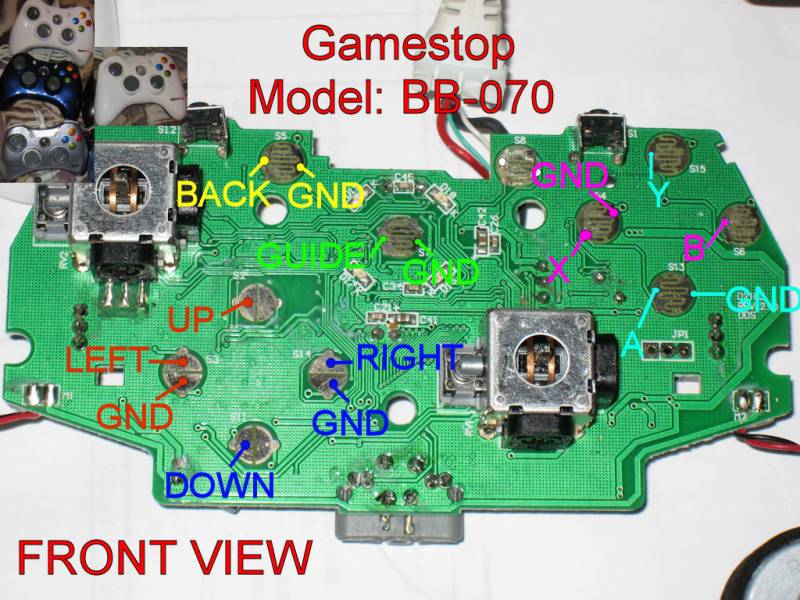
Can someone please tell me if this version of the gamestop controller have common grounds?

Unless someone is psychic without seeing the actual board I would not expect anyone to be able to tell you if that pad is common ground.
If I can find an Xbox 360 controller for cheap, I’m gonna try this, I just hope it doesn’t have any problems with lag or what not.
Can someone PM me if they have successfully hacked a Joytech NEO SE controller with the triggers as well?
I have one coming and would like to know where the common ground is? and how to hack the triggers?
Thanks
Ok I just answered my own question.
It is NOT common ground… too bad cus it was on sale.
Someone correct me if I’m wrong, but all you’ll need to do is connect the 5V for the stick to VCC from the USB on the pad.
Toodles does make a board for the purpose of using a p360 on a non-common ground pad, but isn’t that one common ground? If so, just wire it up, nothing special needed.
Thanks man I appreciate the help but I just scraped it. Thank though. But I’m going to send you a pm about something else.
Yea, my buddy just picked one of these up and Ima have to solder it up for em on Thursday. I had opened another thread to ask some misc questions, but on second thought it makes more sense here, so lemme paste this
http://www.joystickvault.com/showpho...to=451&cat=507
Although Im a little confused. Does this mean I can save some ground wiring by matching the colors?
left and up, down and right, Y and A, X and B?
Also according to the back view, he talks about triggers. Ill assume he meant those are the bumpers? in which case RB can go with Up+Left and LB with Down+Right?
And finally, I see no markings for the Start button. Ill guess no common ground with that one?
So Im hoping if I understand this correctly Id only need to solder about 7 grounds then?
L+U+RB, D+R+LB, Y+A, X+B, Back, Start, Guide?