After searching this thread for hours I’ve been unable to find the answer for a question i have: In making an 8 button 360 stick, would it not be possible to use the right and left analog stick clicks to avoid all the extra work to make the triggers useable? I’m a little too worried about my soldering to tackle making the triggers use able.
ON AN UNRELATED NOTE:
This is my first post, despite reading the forums for quite a while, and i just have to say the wealth of information on this site is incredible great job everyone.
Also sorry if this question has been beaten like a dead horse, and i’ve just missed it.
It depends if your pad is common ground. I have no clue if it is. If you can find a PS1 Dual Shock pad that will be and will work nicely for a dual PCB stick.
Sorry, but no. This isn’t a bad idea but those buttons won’t be mappable in-game even if it works.
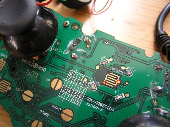
Okay I don’t have a Camera right now but my guide button on my retro arcade PCB keeps activating my a button. I desoldered everything and cleaned up some of the sloppy soldering and it still keeps doing it. Help please.
is there a guide to wire up a SF4 fightpad? Even though it cost more, i was thinking of getting one since it seems it would be easier to wire up triggers as well.
Oh I was just wondering if you had soldered/glued those wires to the PCB in that pic.
Also GameStop has the Mad Catz Arcade Stick (the dopey hand-held one) for $9.99, and I used it to complete my very first padhack and it worked on the first try :rock:
Hey everyone, I’m fairly new here, but I’ve been watching for some time and saw how helpful everyone was being. As I’m sure many others have discovered it’s difficult to get your hands on any of the Madcatz fightsticks or pads so I figured I’d bite the bullet and build my own. The only pad I could find however is the one pictured above, which seems like a good one for wiring. If I’ve read right it’s a common ground PCB and the pads are large enough that soldering should be pretty easy. But I’ve got a few questions…
Essentially, with the exception of the triggers which will have a ground for each of them, I was planning on using one common ground wire for the directional buttons, one common ground for the start/back/guide buttons, and one common ground for the A/B/X/Y/RB/LB buttons.
I just want to make sure I understand the concept.
I would take a wire from a ground and link it to the ground post on each of the 4 joystick switches, and then wire each of the signal pads to each of the “OPEN” posts on the joystick switches. So how do I know (on the above PCB) which directional pads are the signals and which are the grounds? Has anyone got an image of this pad with them labeled?
Essentially I would do the same for the A/B/X/Y/LB/RB buttons (one ground linked to each pushbutton and one signal to each as well) but I have the same question, how do I know which is ground and which is the signal on the PCB.
And lastly for the triggers I will simply set the POTS to neutral and hot glue them that way and then wire one ground and one signal to each of the pushbuttons for the LT/RT to work as a digital switch (thus eliminating the need for the resistor solution). Again, what is ground, what is the signal?
And my final question…Does the above description accurately describe the correct process for wiring this thing up??
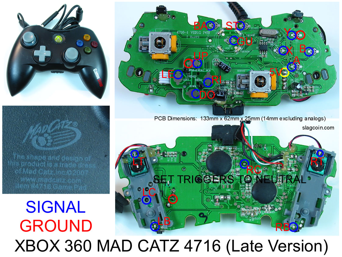
I’m using a new 2008 Mad Catz 4716 360 pad and the triggers don’t seem to register if i keep the pots in, i kept them so i didn’t have to go buy resistors, but they still dont seem to work. Also if i wire the back button to another pcb( like a PSX one) the back button wont function as well as the entire other PCB. I can live with no back button, but what can i do to get the triggers to work?
This is crossposted from another thread, in hopes the padhacking thread would get me some much needed help:
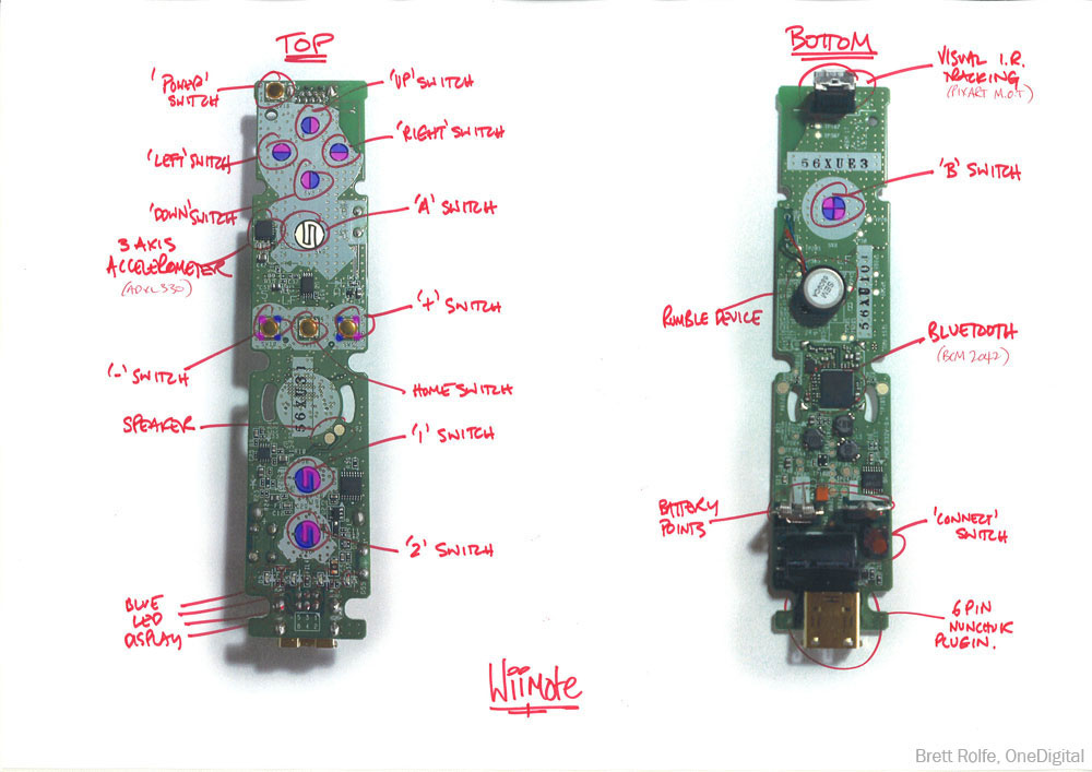
TThere’s actually very little information on hacking Wiimotes in the forums. The SSB stuff was mostly people talking about getting analog function to work somehow, not anything on actually hacking the pad. (You guys need to check out Wiibrew.org. There’s SO much stuff there that demands a good D-pad controller for the Wii)
This diagram was the most substantial bit of information I could find, and pretty much all I need, since I’m not interested in anything besides the basic digital Wiimote functions and pointer. Can anyone tell me where I’d need to solder to get the Home and Power buttons working? I haven’t cracked my Wiimote yet, and I don’t know what on earth to do with those weird gold pads.
Also, a couple newbie questions:
How do I “Dremel out” those weird Y-shaped screws?
What sort of wire or ribbon do I need to let me desolder and reattach the IR pointer to the outside of the case?
How do I keep the battery pack and sync button after taking apart the controller? I plan on using an old sturdy plastic VHS case, so I can open and shut it to change the battery if need be.
THat is odd. Did you test out the stick before you disassembled it to make sure it worked correctly to begin with? Seems odd that it’s activating for no reason.
Yes I tried the retro arcade before takeing it apart. I backed tracked everything and I still could not get it fixed. I just scraped it. Hope fully I can some money in a couple of weeks and order me a pre solderd 360 pcb and a Cthulhlu board to finish up the dual mod. One more question though I’m using a switch and when i splice the usb cord the black go with the black and red with the red witch are the 5v and ground. Do i still need to run 5v and ground wire from the PS3 pcb to the 360 pcb even though they are conected at the usb.
heya,
i was poking around my board with a couple wires on the end of a button/switch to figure out the ground and signal points and everything was fine. Then i got to the guide button, it was all working well and good, then i came back to it half an hour later and it was no londer working!
i have no idea whats happened, i’m gonna have to buy a new joypad arent i?
the pcb is from a Joytech NeoSE (not common-ground), i’ve been poking wires on the points marked red on the picture.
please, if someone could let me know what i’m gonna have to do, obviously not buying a new controller would be great.
I looked for that one first, but not one place in my area had any, and I couldn’t find any online. I think they are pretty much done for. If you see any, I’d buy em all, cause I’m thinking you won’t be finding any again…
In an ideal situation, id like to get the triggers to work, but after searching i’ve only been able to find bits and pieces on what have to have do, and im just worried that I’ll do something wrong and be out a pcb (or worse). So my next question is, if anyone has a decent guide to soldering up the resistors for the triggers on a newer madcatz 360.
Again, I’m sorry if this has been answered 1000 times already, especially with the flood of interest on sticks with sfiv out now.
I have someone who is far more experienced in doing surface mount soldering than me who is willing to attempt a padhack for me. I’m going to go to the store tonight and pick up a pad or two for him to work on.
Question:
In your collective opinions, what is the best pad to use. I’ve read this thread quite a bit and i do understand that i should use a common ground pad, but from my understanding there are quite a few, and i wanted to try to prioritize, picking up the pads which will give the best chance for success (largest solder points?)
Seems like the ordering might be:
-madcatz Fightpads (subject to availability)
-crazy atari stick looking controller
-gamestop (madcatz) controller
-standard wired xbox 360 late model controller
I joined the USB 5V and the USB ground point on my hack, but I still connected a ground point from a button on the 360 pad to a ground point on the terminal stripe the SE PCB uses. It works fin for me.
Also on your Retro PCB issues, I’d suggest conecting just the PCB through USB then jumping a couple of thr button contacts to see if they activate just that button or the guide button also. Then you’ll know for sure if the PCB is still in good condition.
If you look back through the thread (or find the Soldering a MadCatz Fightpad thread) you will find a picture of my hack of that particular pad. Fairly easy except for the guide button, find an alternate solder point for the guide if you can.
Does anyone have a good diagram or can make a fast one of the soldering for a non common 360 wired pad? like the buttons and daisy chain and all? also im cutting the jlf pcb too, and having 6 buttons and 3 start select ect buttons
You are SO in luck. I did this at work the other day. Black is ground except for a couple of points where I messed up which is ground and which is signal (the X and B buttons). Also the right trigger isn’t wired properly since there isn’t a resistor.
I could be wrong, but I am fairly sure that on a non-common ground PCB you cannot daisy chain the ground. However, again I may be wrong in that thought.

