Hmmmm. I have tried both 4.7k and 10k resistors on my Madcatz 360 triggers and neither seem to neutralize the triggers. The resistor connects the wiper and the high voltage, and the signal wire for the button is attached to the wiper. Ground for the button is just the same daisy-chained ground as the rest of the buttons on the pad.
The result? When I press a trigger button it will activate some other buttons plus some direction on the analog stick. This mimics what I observed on my first padhack (where I left the pots on) when I didn’t have the dial adjusted to the right resistance.
Hi all, I recently purchased a Joytech NEO Se control pad for the xbox 360. I was wondering if anyone had a PCB diagram that labeled the ground and signal soldering points. Below is an image of the PCB from an earlier post.
Can someone please help me figure out how to remap the LB, RB, LT, and RT buttons on a Street Fighter IV FightPad? The default layout sucks and I want to fix it. However, the traces are really tiny and I can’t figure out which is signal and which is ground.
I Hacked a mad catz retro stick and for some reason the guide button stays on. when i close the guide screen it opens back up. After this I disconnected the guide button and when i push the other button the guide button activates.
If you have a multimeter (which everyone working on a joystick should have) you can set it to continuity mode and do some trial to see which is signal and which is ground.
Also can’t you just change the buttons in SFIV, or am I misunderstanding your intentions?
if u don’t have a multimeter u can use a diode (as in 1N4148), current only goes one way so touch both contacts with each end of the diode and it will activate the button if the signal is touching one of the correct contact/
I believe, according to [media=youtube]9Km1P4wM480[/media] video, that the wiring on the PCB should be (from top to bottom) open, signal, ground. Take a wire from the signal point, wire it to the appropriate place on the button, solder a 10k resistor to the ground terminal on the button, and then from the resistor to the ground on the bottom hole on the PCB. Otherwise if you’re not planning on using the trigger buttons in-game, just leave the potentiometer on the PCB and take the trigger mechanism off.
I’m hacking a wireless 360 pad. Everything’s wired up except the directions…How do you guys get a secure solder on those tiny points? Do I need to hot glue over every direction point?
I recommend heating the copper point and wire with the soldering iron before applying solder. Do this using alligator clips or something to hold the wire in place. Heat the wire and copper point by placing the soldering iron on top of the wire and pressing down slightly, making a “sandwich” with the layers being soldering iron, wire, copper point. After this (while still holding the soldering iron on the points mentioned) touch the solder to the top of the soldering iron and the solder should run straight to the points you heated up. Hot glue afterward.
has there been a list of the cg 360 wired controllers made yet? Ive been looking for a madcatz and cant find any at my local gamestop, walmart or target. At GS they have the ones with game stop written on the grip and a other brand, joytech or something.
The GameStop branded sticks with the pointy-ended grips are just re-branded madcatz and should work just fine. Check this out; it’s got the GameStop branded pad.
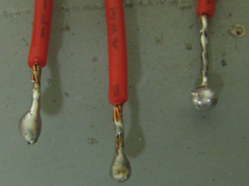
I just thought I’d post a pic of how I tinned my wires for my gamestop/madcatz 360 padhack. I used .22 guage stranded wire and tinned with .050" 60/40 rosin core solder adn a 25watt soldering iron.
When tinning, I gave each wire tip a pinhead sized blob of solder hanging off, and used this tiny blob to connect the wire to the pad, as opposed to trying to manage to hold my iron, the wire, and the solder all at the same time. I hadn’t seen anyone else describe doing it like exactly that (though I’m sure it’s been done), and I thought is was real easy, especially considering this is my first PCB soldering job.
You can see the rest of my padhacking pics at
warning in the first couple pictures of the soldered controller, the “B” button has the wrong contact soldered. It was the last button I did and I guess I got excited and didn’t double check. You can see in the final picture though where I fixed it. I just didn’t want anyone to look at the pic and use the wrong B button in their own soldering job if they have this PCB.
That is one way to do it. What I did, though, was to tin the wire with a very thin layer of solder, then apply a small blob to the contact itself. That way, you get a good connection with both the contact and the wire, then you just melt the two together.
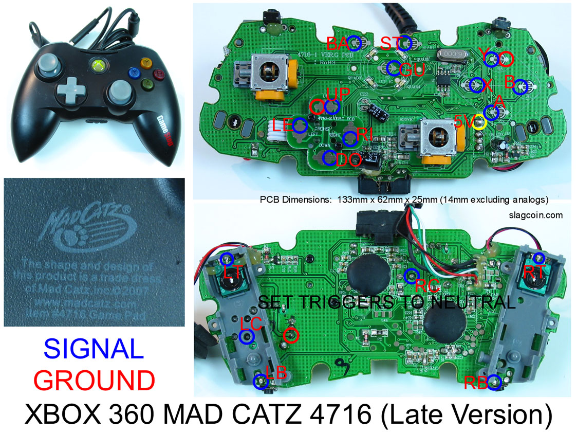
These are what I use as well. If you go buy one today it will more than likely be a 2008 edition versus the 2007 in that Slagcoin link. Here’s a diagram for it.
This is the right way to do it. Tin the wire, tin the point, melt them together. I’m not cocky enough to criticize the guy above, but every soldering tutorial I’ve ever seen/read does it like this.