thank you I have the common ground 360 controller yessss:lovin:
Does anyone know where I can find a guide to removing the analog sticks from a Mad Catz 360 PCB?
who knows where the signal and grounds are for the RB and LB on a gamestop bb-070 pcb? I would guess the signals are the same as the OEM microsoft wired PCB, but how bout the ground? does it share a common ground with another button? The joystick vault diagrams don’t show it.
[media=youtube]9Km1P4wM480[/media] might have some answers for you.
Any ideas on extending the guide button from an MS 360 (wired) pad?
What im wanting to do is take the guide button (and surround) from the pad and poke it through the top of my stick case. I know I can solder a momentary pushbutton to the points on the board to act as the switch, but im wanting to keep the 4 green LEDs working aswell.
There isnt enough room to just have the PCB under where I want the guide button to be, so can I just desolder the 4 SMT LEDs from the board, extend them with wires, and then hot glue to the plastic surround for the guide button?
Didnt want to really do it cos it could get fiddly, but I guess I cant just install my own LEDs cos of the voltage difference?
Thanks guys.
Found something for you explaining exactly how to take those LEDs out.
You should just be able to get LEDs of the appropriate voltage and stick 'em on there.
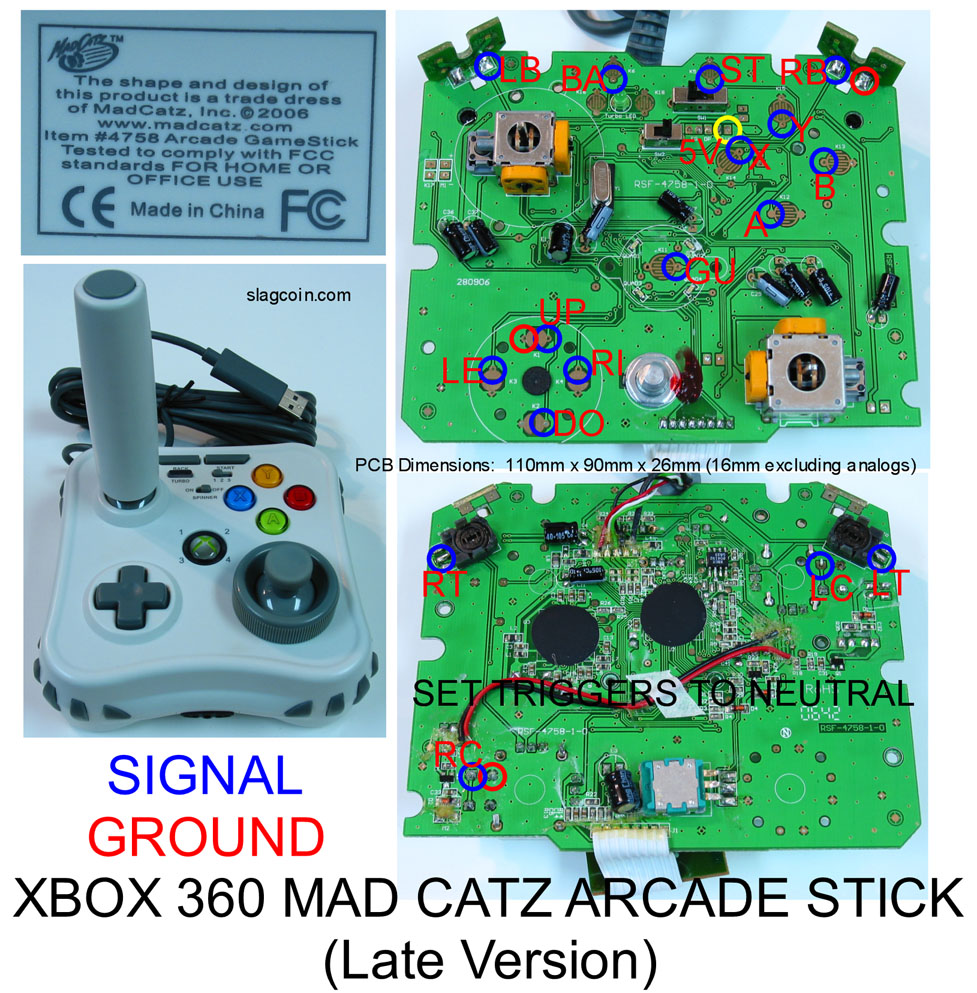
This might be a simple question, but it’s kinda hard to find the answer. On a PCB like this one: http://slagcoin.com/joystick/pcb_diagrams/360_diagram2.jpg
Is the red circle by the RB a required ground or an alternate? If it’s required, can I just split the common ground from the other pad in two and connect one end to the Up ground, one end to the RB ground?
Also, I’m trying to learn how to do analog triggers for my next project. (Converting a Saturn pad to 360, using the above 360 PCB and a Saturn PCB) Is it as simple as removing the old analog piece (the black box that connected to part of the trigger) and soldering in a 5k resistor, then running a wire from one end of the resistor to the other pad?
The red circles are all common grounds, you can use any of them.
Hey all, i’ve soldered all the wires to my 360 non-common ground board, i can’t get the JLF-TP-8YT to function, all the buttons work except the joystick
Below is a picture of my JLF PCB and a diagram of how i wired the JLF Harness to the Xbox 360 PCB.
My JLF PCB
http://www.stooorage.com/thumbs/82/98026_img00346.jpg
Diagram how i wired the JLF Harness to Xbox PCB
http://www.stooorage.com/thumbs/82/98023_pcbmine.jpg
I cut the traces on the JLF following this did i do it wrong?
http://forums.shoryuken.com/showthread.php?t=183966
Also when i switch the wires over for the UP direction and i switch the wires for the LEFT direction, the joystick works up and down only, left and right does not work, so confused =/
Hope this made sense, please anyone help me?
How come you’re soldering directly to the PCB when you have the harness? Can’t you just take the black wire and daisy chain the grounds? I must be missing something here.
read this
http://forums.shoryuken.com/showthread.php?t=183966
i don’t have a common ground Xbox 360 PCB, the wires from the harness are my Signals and what you see on that JLF PCB pic soldered are my grounds to the Xbox PCB
It’s a non-CG board, so he needs four separate grounds.
Have you tried running a wire from each individual microswitch, to see if it’s a problem with them? Other than that, is it possible you’ve severed the signal traces as well?
Anyone have desoldering recommendations? I need to remove an IC this afternoon and thought I’d come check in before spending more than I have to. Rat Shack has a sucker, bulb and braid. From what I’ve read it sounds like I should try the sucker first. I’m thinking I’ll be less inclined to screw something up with that than I would with braid.
:bluu: Well goddammit, I thought I was gonna have an easy-ish time soldering my own, and now this. Oh well, thanks for the info, guys.
I found the perfect video for this using a desoldering vacuum, lemme find it … [media=youtube]Dr55psOlL-I[/media]. That goldish apparatus goes for ~$10 at RadioShack and looks like it does a great job. There have been reports of it not being very sturdy, but if you’re like me and don’t plan on desoldering a lot of stuff (maybe 3 360 PCB’s worth of triggers), seems like the way to go.
i haven’t tried running a wire from each individual microswitch trying to work out if i did my wiring wrong or if i damaged my JLF PCB, how do i know if i severed the signal traces?
i know this wiring diagram is for a common ground board, but should i wire only the directionals like that for a wired Xbox PCB?
Thanks, yeah, I won’t be desoldering much. That looks easy enough and was extremely helpful. 
Another (possibly simple) question: What kind of resistors can we use to fix the analog triggers? I went to Radio Shack armed with one piece of information - “Get 5K resistors.” When I actually look at the shelf, they come in 1/4 watt, 1/2 watt, and 1 watt versions, and some of them say stuff like 5% tolerance. I’m about to head back in an hour, after Googling a little bit. Are any of these okay for neutralizing the triggers? I couldn’t find 5K either, only 4.7K, so I was going to just get the 10K ones that were 1/2 watt. Am I making any mistakes?
1/4 watts in a 5k resistor requires 40 volts, so I’m pretty sure any of those will be safe.
5% tolerance doesn’t really affect you too much either.
5% tolerance means that they can be 5% off of 4.7k on either side, but it rarely ever matters. AFAIK, 4.7k is just fine, and 1/4 watt will be also just fine.
edit: beaten!