Ok!!! I have been using the ‘search thread option’ with keywords like: “sanwa joystick madcatz pcb” and “universal 5 pin connector” but I haven’t found a direct answer.
Do the Sanwa joystick’s 5 pins consist of 4 directions and 1 common ground? What is the best way to connect to the 5 pins? Should I solder directly to them or use some kind of terminal set up?
Thank you for the help. Where do I get the JLF_H harness? Does it come with the joystick or do I order it seperately? I haven’t acquired my sanwa joystick yet.
Is there any other xbox 360 wired remotes that are common ground? theres no gamestop in canada and ebay doesnt seem to sell the arcade ones or the normal common ground either, and dont want to take a chance buying a microsoft brand one on ebay and getting non common -_-
I just started lurking this forum today ^^; and first I’d like to thank many of the people for making the tutorials and helpful images on this forum.
I have some experience in soldering from tech ed class in mid., school so I don’t have much problems with soldering but… Looking at this images, I get confused @_@
What is the purpose for the 3.3volt spot? Will I need to solder a wire to it or anything?
But people all say the older ones, with the madcatz logo in a circle at the right part f the controller isnt common and the one that says gamespot is, and they dont sell the gamespot ones nor on ebay that ships to canada
Hmmm…the one I posted earlier in this thread sure was common ground…
Contact this member: zombie qpt
He may be able to help you…he offers pre soldered MC PCBs for the 360 for a VERY VERY reasonable price and the work will be 1000x better than pretty much any of us could do.
I would like more info on which madkatz 360 pads arent CG. Need to put a 360 pcb in a fs3 and im pretty sure theres not gonna be room to throw the retro stick pcb in there.(Dual Pcb)
Thanks
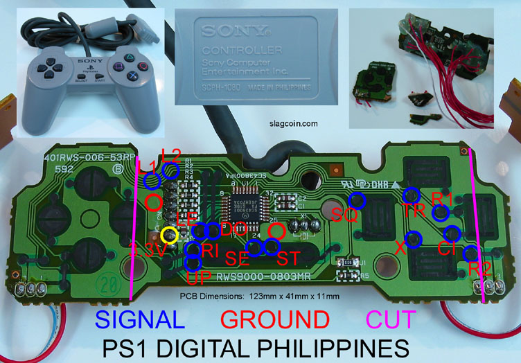
Hey guys, quick question about the PS1 digital Philippines PCB. On slagcoin, every necessary solder point is pointed out clearly except for L1 and L2. He circled parts of the traces, but no specific lines are scratched out for reference.
If you take a look at it (here) you can see that the designated areas are circled but ambiguous.
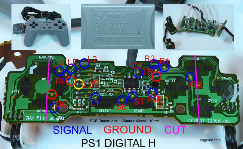
Compare it to the PS1 digital H PCB (here) the areas along traces are scratched out and obvious.
Can anyone help me out? If possible, please edit the slagcoin pic to avoid any sort of confusion.
Ok ran into a bit of a snag, everything works perfect except the triggers, i have a Madcatz 4716-1 not the newest one where u need funky resistors and capacators to make it work, just resistors, every other button, inclueding the guide works perfect, and the triggers seem to be in the always off, which is good, but when i earth out the trigger, past the resistor, nothing happens, tried both ground, front and back still no dice, here is a pic of what ive done, is it right or what have i screwed up?
I have a pre-soldered pad i bought a few years ago i never used. I bought it from red octane, it is square with JY-006-2002-10-31 written on it. I am not sure what goes to what and where the cord for the PS plug attaches.
I am going to post a pic of it when i get home, Thanks for the help guys ^^
Can I get some help with wiring the triggers on the gamestop bb-070 pad I have every thing else wired up. The pic on joystick vault don’t make since to me.
^ im not an expert in 360 pads but the 1st one looks like the one i got which is not common ground
now i just hacked mine yesterday and by some miracle it seems to work great but i only tested it on PC, would it act any differently on the 360? i dont have a 360 so i cant test it yet so if anyone could tell me it would be very much appreciated…
![[IMG]http://img26.imageshack.us/img26/5719/01042009288.th.jpg](http://img26.imageshack.us/my.php?image=01042009288.jpg)