Yes it can and all the info is here already.
Plz search, you are already in the right thread and subforum.
Yes it can and all the info is here already.
Plz search, you are already in the right thread and subforum.
Have you looked at RDC’s diagrams from xbox-scene? You want the yellow line with the black dot.
I did all of my d-pad connections with trace wire through the via points on the board. Need to open up the holes a bit with a pin or a pick tool.
http://i50.photobucket.com/albums/f320/RDCXBG/Repair/360CGWirelessBoardTop.jpg
http://i50.photobucket.com/albums/f320/RDCXBG/Repair/360CGWirelessBoardBottom.jpg
I understand I am in the right thread but it is over 100 pages long. Is there an easier way to search than reading the whole thing? If not, is it unreasonable for me to ask for help?
Thanks!!!
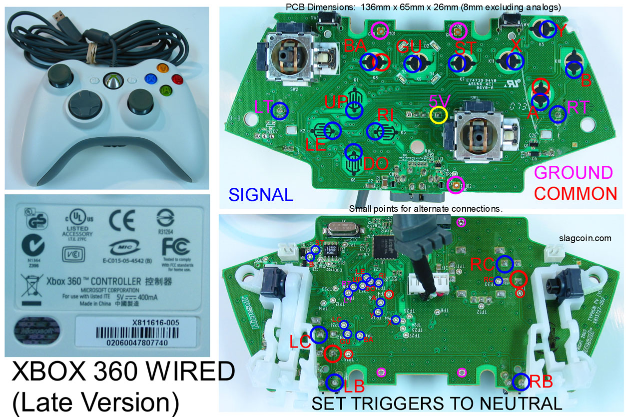
from my reading with the late version of the official microsoft wired control pad pcb you can daisy chain everything to the common grounds?
And for the early version of the official microsoft wired control pad pcb, you have to solder 2 wires to the pcb say for example “button A” then 2 wires to the arcade stick button?
So is it better off getting the late or early version of the PCB? don’t have much experience with soldering and don’t understand the daisy chain =/
Those were the pots that you removed. On this controller, the pot is used to signal grounded when unpressed and high when pressed, so desoldering the pot entirely shouldn’t cause it to register pressed always. That problem is generally on controllers that have the triggers the opposite, high when unpressed and grounded when pressed, like the official MS controllers or older MadCatz. Desoldering those causes the pin to have no voltage, when it expects voltage to signal that it’s not pressed, so the controller acts strange or has the triggers always pressed.
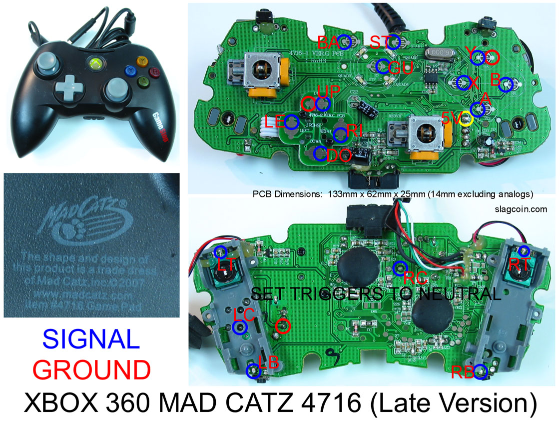
TL;DR version: You should be fine if you removed the pots on that controller. It’s common ground and a rebadged madcatz pad with a slightly different shell, it’ll work great.
Have a quick noob question. I am about to do start the soldering part of my Anniversary Stick mod. I have my 360 controller opened up to the PCB. I am going to use this diagram:
I already installed all the Happ Competition parts.
Being that the 360 controller is a common ground controller, I can solder one wire to any ground point on the 360 PCB and daisy chain them to the buttons and joystick?
or
I can solder one wire to any ground point on the PCB and then us one of these:
Hook up the ground to one point on the terminal strip and run a separate ground wire to each microswitch?
I am going to use disconnects on the buttons so doing either method shouldn’t be too hard. Just need to know if either will work?
going off this diagram and if i get the grounded xbox 360 PCB, which wires should i buy?
http://smg.photobucket.com/albums/v701/busdriver_68/?action=view¤t=joystick.jpg
should i buy a bunch of these for the connections?
http://www.in2amusements.com.au/shop/index.php/13/236_Wire_Coloured_With_Quick_Connector_.110_Size
OR this harness
http://www.in2amusements.com.au/shop/index.php/13/233_Wire_Ground_Harness_Suit_Sanwa
http://www.in2amusements.com.au/shop/index.php/13/136_Wire_Ground_Harness_With_30_Connectors
i think the diagram above is daisy chained? i don’t know how that works :looney:
On the PCB, if you have a common ground, a daisy chain or a separate wire run from the same ground to each ground on the controller will be functionally equivalent. I’d personally go the daisy chain way, but they both work. The separate wires to the same ground might look neater.
The buttons and joystick can use the same ground as the PCB.
This diagram was meant for 2 PCBs, but if you get rid of the second, it would work with just one:
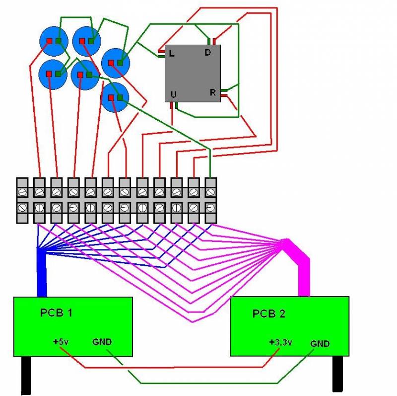
I hope that made sense 
anyone know how to wire the battery to the wireless 360 pad?
yeah just cut out the batter holder from the shell, attach it to the pcb and install the battery
problem solved 
Four quick questions regarding the modding and soldering of a Xbox 360 Mad Catz Late Version wired PCB. Please help cos I’m stuck !!
I know the PCB has a common ground but it still has 3 separate ground solder points ( the first next to ‘up’, the second next to ‘Y’ and the third on the back of the PCB on the right hand side of ‘LC’) - mt question is do I need to daisy chain all 3 together or can I simply choose 1 of them and ignore the other 2 altogether?
Also, if I wanted to ignore the 2 triggers (‘LT’ and ‘RT’) as all I need are 6 buttons - can I simply ignore these solder points entirely or would I need to use resisters to neutralise them?
Would I need to solder the ‘LB’ and ‘RB’ points from the back of the PCB or can I access the solder points from the front?
Will a wire harness from the stick work with this PCB or will I need to forget the harness and solder each individual switch contact at the joystick?
Thanks in advance.
Just confirming i have this pad http://www.slagcoin.com/joystick/pcb_diagrams/360_diagram3.jpg, so with trigger pots fully off, connect a 10k resistor between voltage and the middle ‘wiper’ post of the three petentiomiter solder spots, leave the ground alone, connect the wire for the button on the wiper side of the resistor and bobs your aunty? :tup:
I daisy chained all my three grounds (main buttons, start/guide and joystick) to the same place, which was the right hand side of the down contact via a terminal strip. There are grounds all over the PCB, just pick one or however many you’re comfortable using.
You can neutralise them by simply connecting the pad to a PC and turning the pots until the button isn’t activating. Then you can glue them down and/or map LT/RT to ‘no action’ in SFIV. I just kept them unglued.
I used the back; the front solder points are a little too small IMO. Should be possible though.
The wire harness just gives you five wires from the stick (directions plus ground). You then solder those wires to the direction contacts or into a terminal strip etc. The whole point of the harness is so you don’t have to solder anything to the stick itself.
The main thing is to make sure you have the right layouts for your PCB. I used these:
http://img293.imageshack.us/img293/5152/pcbfront.jpg
http://img293.imageshack.us/img293/6456/pcbback.jpg
Many thanks to whoever produced them! 
nufc4ever - you are da man. Thank you !!
I am just a little confused still regarding the whole ‘setting trigger pots to neutral’ - could I be cheeky and ask you for a fuller explanation ?? If I am not botheerd about having buttons for RT and LT on my stick can I not just leave this part of the PCB untouched, as it is ??
Thanks again
All it means is that if you remove the pots (the circular bits under the triggers themselves) the PCB thinks you’re always pulling them or whatever. If you do that, you need to solder in a resistor to set the signal to neutral.
If you just want the six buttons, you don’t have to do anything with the pots other than make sure they’re in the right position - off as though you’re NOT pulling them. This can be done a few ways I think but from what I’ve read they’re all basically trial and error. As I say, I just plugged my PCB into a laptop running XP, waited until it installed the drivers from the net and then went Control Panel -> Game Controllers -> Properties (on the pad). It shows you what’s being pressed - this is an ideal place to test your other soldering btw. I turned the pots with a screwdriver and saw the signal changing up and down. I turned both until the signal was in the middle and left them there. Worked fine.
I have never done anything remotely electronic in my life so am tryly grateful for your advice - thank you. When you say the circular bits under the trigger. Is that the 2 black slotted circles on the underside of the PCB ?
When you say turned them until the signal was in the middle, is that simply somewhere between off and on i.e. neutral ?? Once at this point will resistors or any other wiring still be required ?
Also what if I wanted to wire up RT and LT to buttons and use them ?
I am so sorry for all these questions but just want to get it right first time if possible.
Yep, that’s 'em - the circular slotted bits of plastic. Use a small screwdriver and they turn either way. In XP there’s an axis monitor that is like a bar. When I plugged my PCB in it was already say 5 units high. Turning the pots made that bar go up to 10 units or down to 0 units. It’s hard to describe.  Once you’ve established they’re set to neutral there’s nothing else to do unless you want to glue the pots so they definitely can’t move. This seemed like overkill to me though.
My build is here if you fancy a look: http://forums.shoryuken.com/showthread.php?t=183294
If you want to use LT/RT as buttons there’s a bit of work to do, see this thread: http://forums.shoryuken.com/showthread.php?t=169203
Typical - can’t access the pictures at work. I will take a look as soon as I get home. Does the stick work well - sturdy, accurate, better than a pad etc etc ?
I am so keen to get cracking on mine, I have all the art work and box sorted. I am just waiting for the parts from Gremlin Solutions.
To be honest, as this is the first electronics project I have ever done apart from wiring up my turntables - I am shitting myself about the soldering etc etc. If I was struggling too much would you be able to recommend someone to do the wiring work for me? Obviously, I am happy to pay for the work. I am worried that if I bugger it up the parts will get damaged and will need to be replaced. When you look at 20 for the another mad catz controller, 20 for another joystick - these would be expensive cock-ups.
Back to these damn pots quickly - on the XP axis monitor - is neutral zero, 5 or 10 ???
Neutral would be 5 on that scale. It’s so much easier when you actually do it. :lol: The other way of course is just to plug it into your 360, go into training on SFIV and turn inputs on. Then turn the pots until the triggers are not showing as being pressed.
I dunno about recommending someone to do it, most on here that offer services like that are in the US. It’s worth searching around though if you’re really not confident. In reality it’s not all that tough tbh, though I was helped by my Dad because three hands were needed. Not sure what you mean about another 20 on the joystick like, if you use terminal strips you don’t have to solder anything on the buttons/stick ‘side’. Have a look later at my pics and you’ll see what I mean. If you managed to bugger the PCB it’d just be another one of those to buy.
My stick’s really nice to play on, I just need to get good…
Very true regarding the stick and buttons etc possibly just a new pcb to buy.
Do you play Street Fighter IV much ?? If so, look me up or send a Friend Request and we can smash the shit out of one another sometime soon.
Thanks again for all your help today - much appreciated.
All the best.