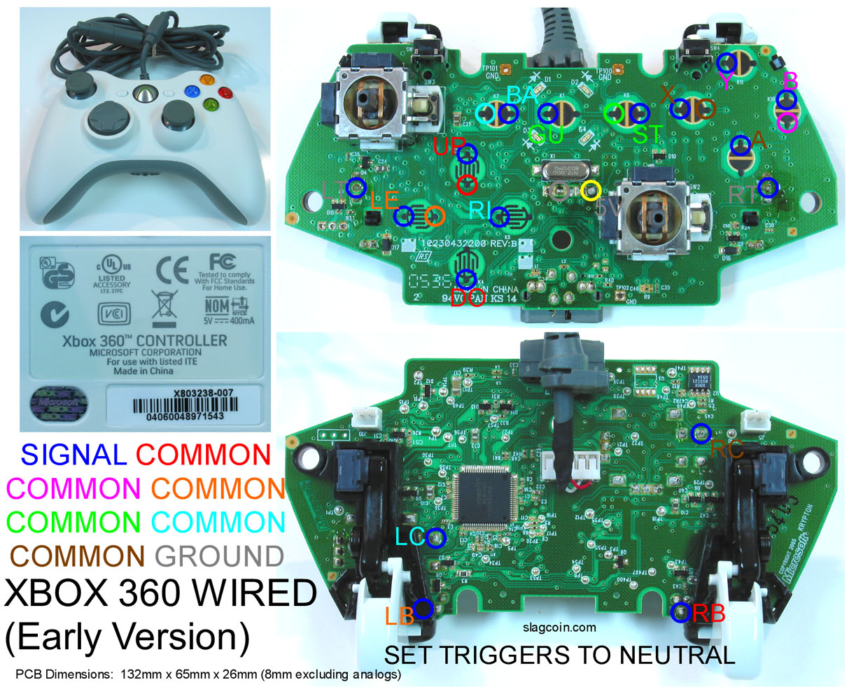
i’m really close to finishing my joystick, but i’m having trouble with my A X and Y buttons. i’m using an early version of the official 360 wired controller, so i used slagcoin’s and rdc’s diagrams.
early on, i wired to both points on the front of the pcb for each button (the two black covered spots), assuming one is for signal and the other is ground. i tested these points by plugging the controller into my computer and going through the game controller properties. putting the wires together seemed to work for each button (button press when together, off when separate). but when it came time to wiring them to the joystick buttons, whenever i tested them the A X and Y buttons would always be on.
does this mean they’re not grounded? i took another look at the slagcoin diagram and realized that A and Y don’t have their own ground, but they’re common with X and B? is this correct?
i also tried connecting A1 and A2 X1 and X2 etc. on the back of the pcb according to rdc’s guide, but i got the same results. the alternate points on the back of the pcb work for my directions and shoulder buttons, however. help please.
I have a late version 360 wireless controller. Accidently I ripped off the copper contact for the up direction. I have looked every where. I can only seem to find the down and right direction points on the back of the controller.
If anyone with experience witht he wireless pad knows the alternate points on the back of the pad I would be forever in debt to you. Even better I you could direct me to a diagram.
This would save me another $50 on this wireless stick project.
What’s the trick to soldering to the little tiny points on the box of an Xbox 360 pad? I used a tip that was too large and both of the large copper pads on the front fell off and of course won’t reattach (buttons Y and B). I’ve been soldering for quite a while but this is the first time I’ve actually had to solder to something this tiny. Any tips?
Ok well I’m pretty sure I scrapped both the B and Y buttons…which is going to make it tricky to back out of practically everything…I actually got the solder points to stick but when I went to connect the wires to my terminal the solder point somehow popped off…even though they were super glued down, and now I can’t get it to solder again…scrapped or still viable for usage?
I did the exact same thing Icee on my first time soldering, I’ve heard that you can fix it by scraping of abit of the green trace leading to the vopper plate to expose some copper in the trace and then soldering to that.
But I just bought a new CL control (wich I have seemed to mess up too)
If anyone have any experience repairing a TP point I’d be so glad hearing a solution
i think that since the pad i am using is a non-standard 360 pad that doesn’t have any diagrams, i should test each connection before soldering. short of just hooking it up to a 360 to test, is there a test suite that you guys recommend for PC?
yeah i posted on the previous page and i have pics of the board and the manufacturer’s label - its a joytech 360 pad. here’s to hoping that it is similar to the madcatz pad.
worst comes to worst, i can just get a madcatz pad and try this again. my biggest concern are the triggers… sounds like if you rip off the little boxes that control that servo arm, it will constantly register as though you are squeezing the trigger. is that true? if so, i am probably fucked unless i can figure out which 2 of the 3 contact points for the triggers i need to run a resistor between.
I have a late version 360 wireless controller. Accidently I ripped off the copper contact for the up direction. I have looked every where. I can only seem to find the down and right direction points on the back of the controller.
If anyone with experience witht he wireless pad knows the alternate points on the back of the pad I would be forever in debt to you. Even better I you could direct me to a diagram.
This would save me another $50 on this wireless stick project.
i am interested in doing a solder-free spiffyshack mod. i opened up my ps1 dualshock controller, which was an A model, but i didn’t find the same ribbon terminal pictured in the spiffyshack tutorial, on my pcb. there seems to be something that connects the membrane to the pcb and something that resembles a ribbon terminal on the back of my pcb that does not look exactly like the one pictured in the spiffyshack pictures. can i still do the solderless padhack if the ribbon circuit board is not the same as the one pictured in the tutorial? doi **have **to cut off the membrane to do the padhack?
i know everyone here hates 2009 members, but i’ve tried searching the forums and haven’t found an answer. this seems to be the most appropriate thread to post my question. thanks for all the help you guys are providing to newbies like me!
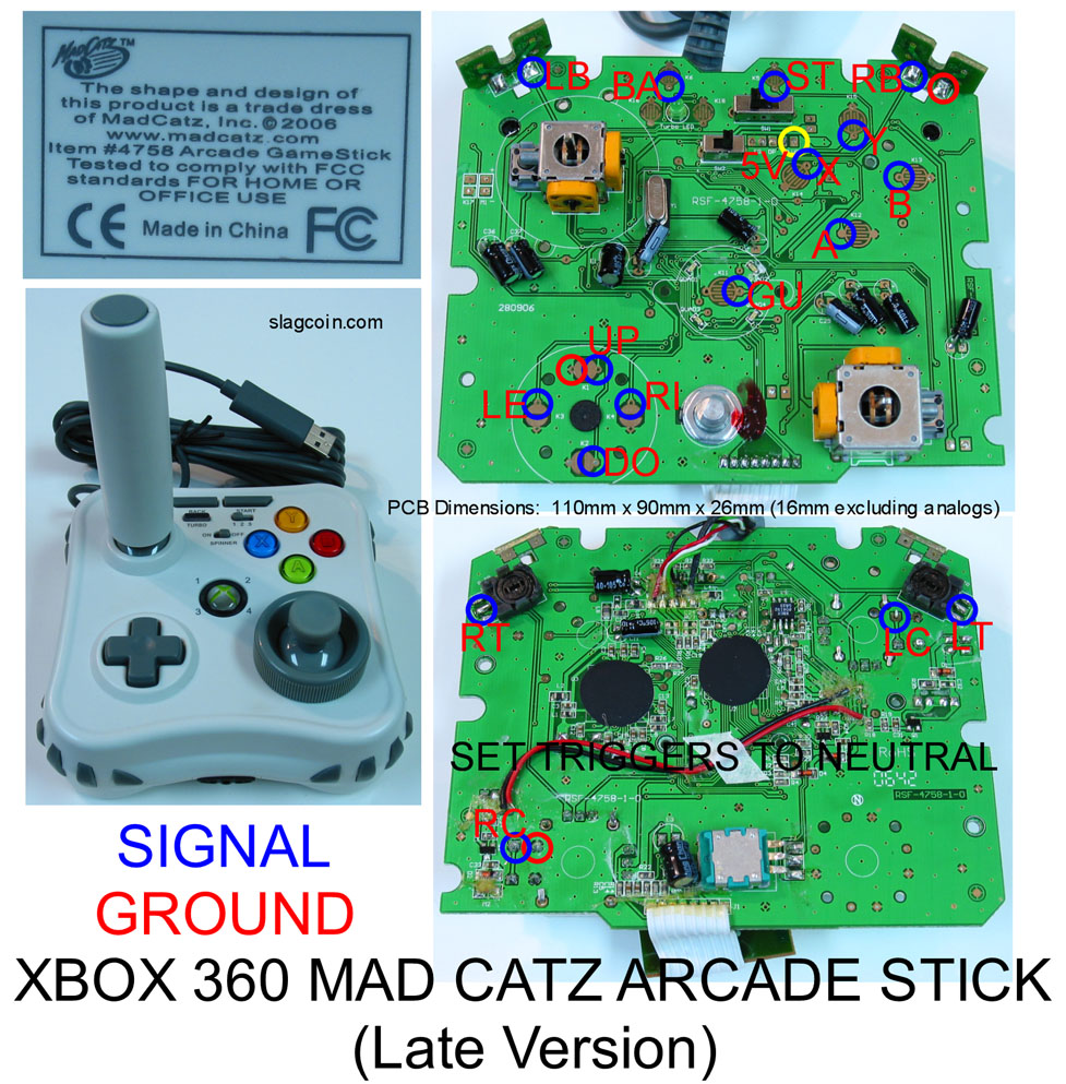
If I got it right ( using a terminal strip) I can hook up one of the red grounds to one side of the strip and it could ground all the buttons/ joystick ? or would i need 2 separate grounds, 1 for the buttons and one for the stick? also on the bottom picture, what are the rc/lc connections for?
I’m planning to do a DIY arcade stick, going to purchase a late version of the official controller just a few quick questions before i make an order.
going to purchase 6 sanwa obsf buttons — how many more buttons should i purchase based on a 6-button layout
sanwa joystick JLF-TP-8YT — hope these are easy to wire to the xbox 360 wired pcb, are terminal strips the way to go with the arcade sticks based on the common ground PCB(late version)?
This is my understanding from reading. I’m going to start my own dual-console build in a couple of weeks.
I’d recommend 3 more buttons, most likely screw ins. You’ll need one for start, select, and the guide button. If you’re building your case out of wood, screw ins will be a lot easier to work with.
The joysticks don’t seem to hard to wire to a 360 PCB. I’ve seen setups with terminal strips and without. I guess its a matter of personal preference/expandability. I think that common grounds can be daisy-chained together, so you don’t necessarily need a terminal strip. If you’re planning on a dual mod though, you’ll definitely want a terminal strip.
in terms of wired controllers, I’d suggest using a late madcatz controller. They’re a bit cheaper, verified common ground, and well documented on these forums.
Again, I haven’t -actually- done my own build. This is just my understanding based on what I’ve read.
thanks for the reply, i can’t get my hands on any madcatz controls as i am in Australia, otherwise i would so the official microsoft wired controller has to be used =)
I’m not intersted in dual-console wiring, xbox is the main console i play, as for the daisey-chain for the common ground not sure how that works, do you run a single wire from button to button then to the ground =/
Would buying something like this help me wire things up?
Search my name in this thread. Earlier this month I also showed a different label from an official MS controller. I opened it up, and it was an early model (non-CG)
Can a Sanwa joystick with universal 5-pin connector be attached to a madcatz wired 360 pad? If so can someone point me to a link that explains how. A private message would be great!

