Ohh sweet deal, thanks Domz.
youre welcome sir :tup:
That’s great. Thanks a bunch!
Anyone have a link to a padhacking guide for the DS3? This thing is ridiculous.
you could make it easy on yourself and get one of shinjn’s or toodle’s axisdapters, they may not work with your particular ds3 because of a connector change at sony but looks like it’d be a snap if you have the right one
So I recently with help hacked a MadCatz fightpad PCB. Here are pictures of the solders. Notice that you do not have to remove the microswitches for the PCB to work for padhack. However, if you want clean you need to remove them.
Front:
Back:

The only thing that doesn’t work is the guide button. Anyone want to take a stab at trying to find an alternate (and possibly easier) guide button solder location on the PCB?
You could solder to the via’s connecting from the d-pad signals shown in your pic. Scrap away (lightly) the via hole to remove a thin layer of green film exposing the copper ring. Use 30 gauge solid core wire. Solder wire in hole (see slagcoin for tips).
Try plugging it into your computer, hopefully you have drivers for the pad. Take a look in the game controllers portion of your control panel, and if there’s a button that’s showing as constantly on, you have a short somewhere (maybe you put down too much solder). If not, and connecting the wire to a ground point doesn’t give you the button press, you probably just didn’t get a good connection. Desolder and try again.
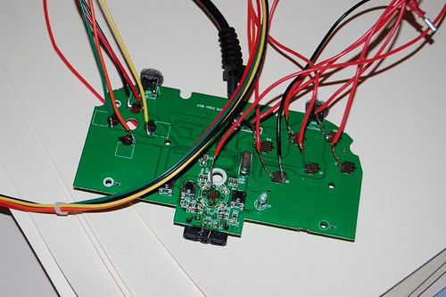
So I’m a noob when it comes to soldering but I am so freaking close to finishing my custom arcade stick so I just want to finish soldering and start playing SF4 again :P. This is the PCB
http://www.clockswork.org/images/DSCN2328.JPG
So what happened was that I did a bad joint and I was about to solder suck the bastard. But being the noob that I am I held the solder sucker to close to the “A signal pad”. The pad ripped off and now I’m not getting a signal from A. Is there a way to fix this? Maybe start soldering from the back? I haver a old wired 360 controller with no common ground.
Thanks 
Just what you may have seen on slagcoin’s website under the pcb diagram section. My suggestion would be to ebay a ps1 controller and padhack it (that way if you do mess up your not out that much cash) Also there are several aftermarket adapters that will make it ps3 and pc compatible (ddr adapter is awesome if you can find it)
ds3’s are notoriously difficult to hack best go cthulhu or third party ps3 pad or adapter.
Directly below the burnt pad is the tiny hole where the copper connects to the board. You can gently scrape off the green stuff and first apply a little solder to the point, then with some solder on your wire, very gently try to join the two with as little heat as possible. Once it’s connected, you will probably want to glue the wires back somewhere else on the board to make sure it doesn’t rip the copper off the board.
Just wanted to say I did my first ‘Padhack’ the other day for my T5 Hori -> Madcatz CG 360. Thanks to the users here, I was quite successful. I want to put a post up with a complete detailing of what I did and how I did it my way just incase it will help someone else.
Thanks to everyone on SRK again.
hey, I need to figure if I can salvage my own padhack at this point. In the process of soldering to the guide button on a MadCatz 360 PCB (newest), the contact no longer seems to work from that point. I know of instances where one can strip away the green to expose more contact, but I wasn’t sure if this was possible. Or perhaps, I’m missing something big and whatever damage I’m assuming that I did (can’t tell, but it’s not working now so I must have done something), and I can do a simple fix and move along. I see someone above had a similar concern, but I guess what I’m looking for is a bit more detail in this case, as I can’t really tell where the lead goes from the contact to begin doing any stripping (if need be).
Were you able to successfully hack this pcb? because I just got this pad from a friend and would like to use this for my stick.
Also do you have a diagram for it?
Hi guys, I am trying to figure out the signal points and ground points on my wired Logitech WingMan RumblePad pcb that I plan to use for my joystick build. It does work on my PS3, so I believe it should be a simple hack, but I just need to figure out what are the ground and the signal points. It is a two sided pcb.
I have included high res pics of both sides of the pcb to help identify the ground and signal points.
Click here for the button side.
Click here for the back side.
Thanks.
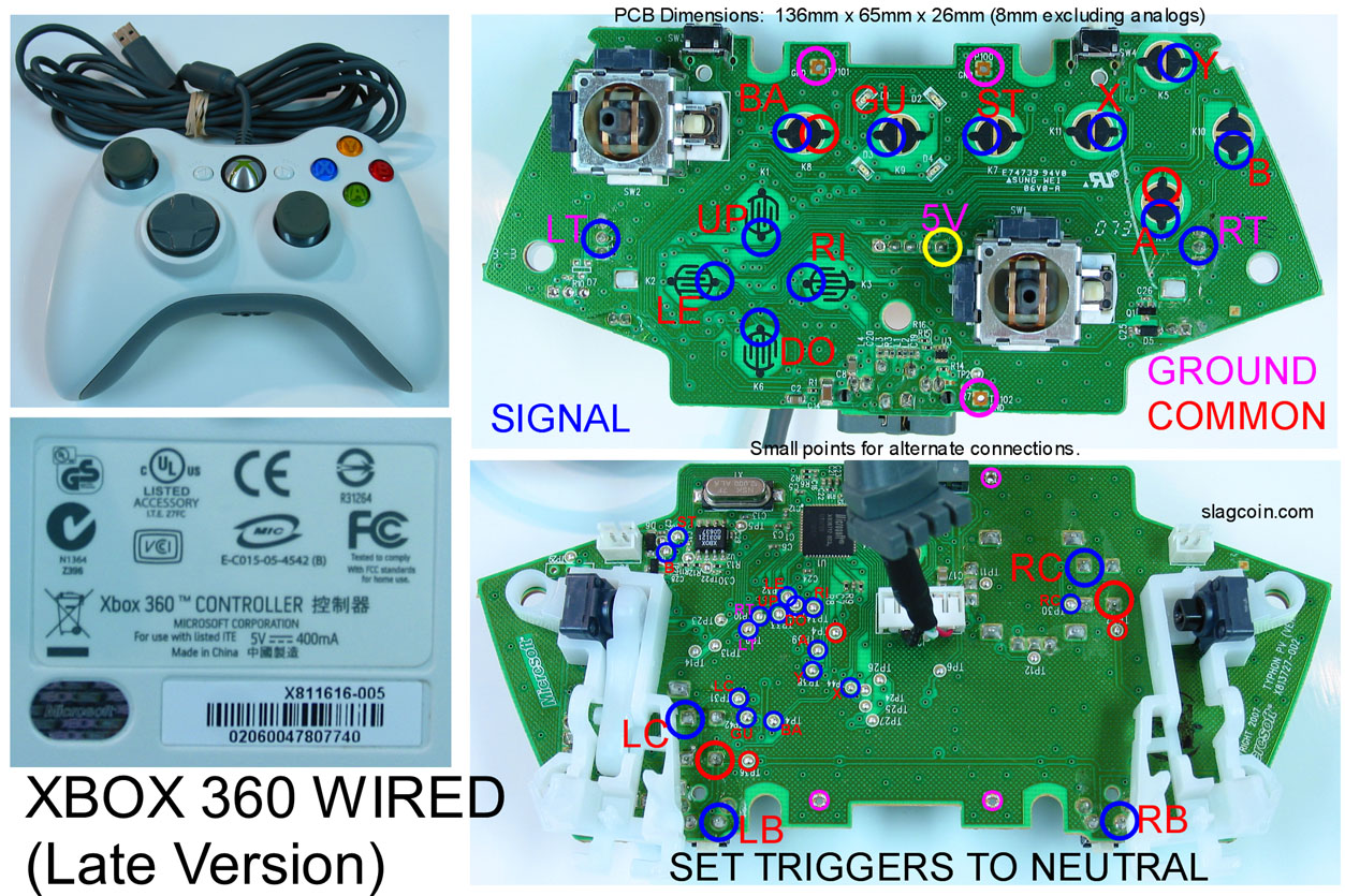
I have a question about this picture, I’m choosing to solder on the top of the pad (with the copper pads) because I tried to solder the TP points but I found that to be impossible :S
Now to my question, where is the ground? And what is the red circle above the Blue A signal?
Thank you 
Also, if you mess up on one side? Say, a copper pad rips off, could you flip the controller over and solder to the TP points?
I’m having trouble getting my A and Home signal to work with a Late version of the 360 wired controller. I’ve tested every button with the common line above the A signal and they work but not the A and Home button, do these button have another common line?
thanks
Also are the TP points at the back connected to the big copper pads at the front?
Thanks
Does someone know the alternative points for the d-pad of a early wired official of xbox360?
can you show us a pic of the pcb?
either way… check out RDC’s threads over at xbox-scene.com
“MATRIX”
“CL”
that should have all the information you need