Where the grounds are on the d-pad, am I able to use the one ground (for example the ground from the Left Direction as grounds for Up, Downd, Right. A quick answer would be appreciated.
hi guys, just wanted to ask about the sync button as i can’t get it to working. I’ve searched the forum and read most of this thread and can’t find nothing. Has anyone actually got the sync button to work?
I’ve decided to try and learn how to padhack, and a friend donated a busted PS2 controller to the cause. Can anyone help instruct me on how to hack this pad?
Hi , Just finished soldering ps1 controller , I use “Boom -PSX USB Converter” and the strange thing with this converter is that START Button don’t work , “X” and “O” is the other way arround, so is “Square” and “Triangle” .
that is not the problem , the problem is if I want to press start, I have to Activate ANALOGUE and press the L3 button it will act as “Start” button".
question: I wired everything and it’s working fine except that I don’t know how to wire the L3 button ( the left analogue click), where is the solder point?
are all madcatz usually common ground? my local gamestop has been clearing out everything lately and so their stock is very limited. they do have a few madcatz pointy; like solid color and some of the sport ones.
Ok i kno this is proly a dumb question but here goes. Im soldering my madcatz retro arcade gamestick and all the buttons except the start button work. i mean the other buttons are perfect, so the question is did i just mess up when i was soldering the start button and if so is there any way to fix it so it will work
Triggers on 360 require using a resistor in the circuit, so a lot of people skip them and just got 6 button. If you must use them, it’s usually a bit more work.
ya that’s not entirely accurate, I purchased a padhack recently and it required no additional resistor but did have a separate ground I don’t pretend to know how it works but it does work and very well at that. here is my thread on it
parabellum, thanks for the reply. I just ended up dusting off the white stuff, and it is fine…
I did have a question for the people with high soldering skill on the 360 wireless CG pad. What is the best way to deal with these tiny dpad points? They are killing me, and I had to use an alternate point on the other side. Is there a more reliable technique for inserting wire into those pin-sized holes on the PCB?
I have a DS3 PCB I could use, but any lag AT ALL is unacceptable for me. Is there any evidence to suggest it does or does not lag. Is it a tough pad to hack?
Can anyone suggest a cheap, lag free, easy to hack pad? I’ll get a chthulu at some point, but which of the third party pads is best, for ps3?
I didn’t want to make a new thread for something this small and simple, so I thought this might be the most appropriate thread for this.
I don’t have much experience with Seimistu or JFL’s so I could use some help here.
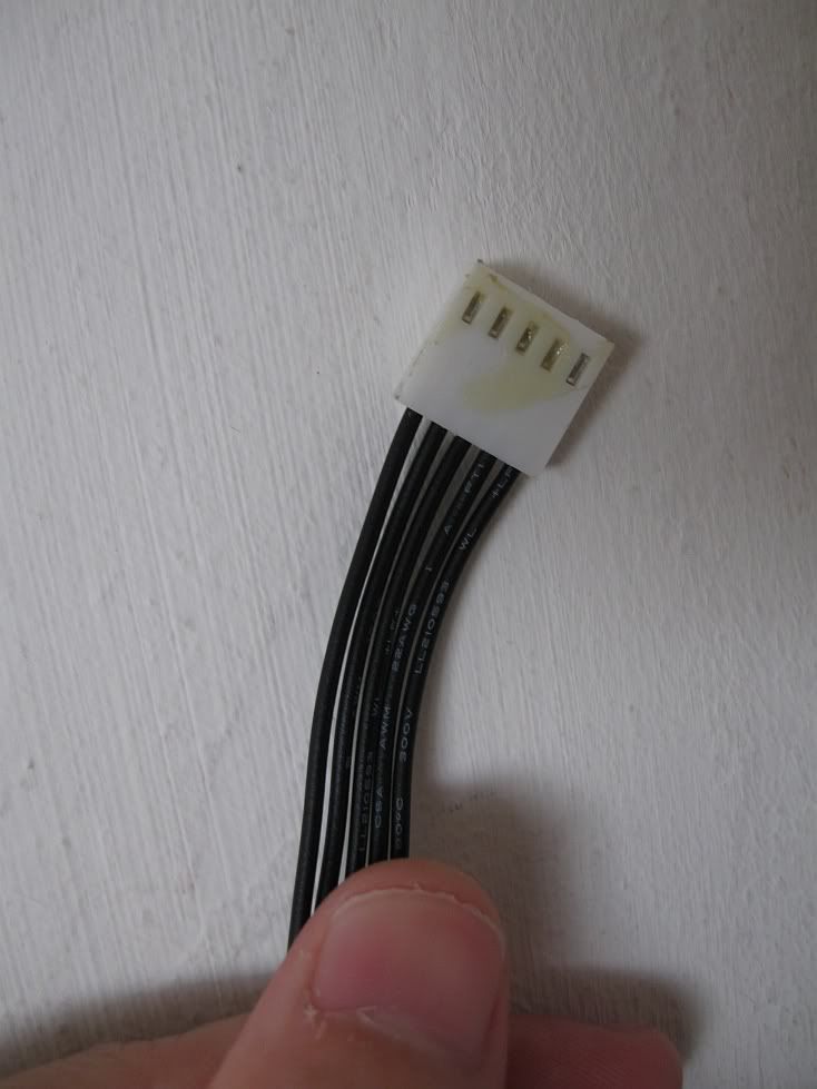
I have a Seimitsu LS-32-01 coming in from LL eventually, but it doesn’t come with a 5 pin harness.
Luckily, I was able to get one from a friend of mine, the one he gave me is from his SF4 SE edition, However I don’t know which wire goes to which direction on the D-pad ((Madcatz 360)).
Also, one more question, If I have to rotate the PCB around, will that effect the wire placement on the D-pad PCB?
Here’s the picture of the Harness, If anyone could just basically red pen the photo, that would be awesome.
http://forums.shoryuken.com/showpost.php?p=5771841&postcount=40
toodles did a test and found:
“What I can say for sure is that anyone using a Sixaxis as the core of their board has nothing to fear from latency. I am seriously impressed with Sony that they were able to pull that off; I did not expect it to perform that well at all. I don’t know whether to feel sad that my board didn’t wipe the floor with the sixaxis, or proud that my board goes toe to toe with Sony engineering. shrug”