It looks to be CG, yes. If you see the face buttons, as well as the Start and Select buttons, there’s only one trace, meaning the other is probably to the board itself, or a common ground.
I’ve got one of these in my Agetec mod right now, can definitely confirm it’s common ground. I think there was an older version that wasn’t common ground, but any of the 4716 ones are. It also has the harder to hack triggers, so if you’re making an 8-button stick you’ll need an NPN transistor and two resistors per trigger.
Thanks for the speedy reply guys:tup:
Bakageta, im not planning on using the triggers so im good, i dont suppose you have a pic of your mod i can check out mate? really interested to see how you wired it up ect:smile:
Hey PCB experts… I just cracked open a 360 wireless, only to find some white spotted corrosion in a few places on the board.
Should I worry about it interfering with my hack, should I clean it off or what??
Thanks, first time I’ve seen this stuff.
Need pics.
It could be conformal coating (if they use it on these pcbs…not sure)…or it could be something else.
Please supply MACRO mode pics from a decent digicam…cellphone pics would be useless.
I got me a $5 used PS1 Digital M pad and plan to start hacking away soon after I swap out the stock parts out of my SE and HRAP3 and have some components to hook to the PCB. Looking at the picture of the guts on slagcoin, the insides should look like this:
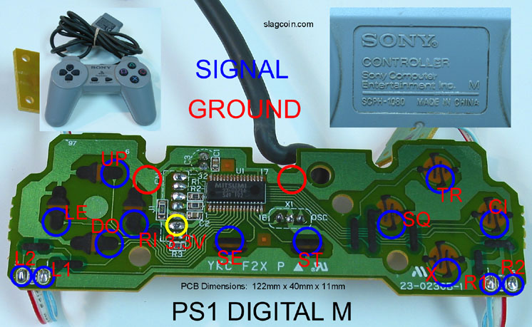
I will obviously have to remove the contact pads to solder the wire for the stick directions, four face buttons, and start and select function buttons. Is scraping with an X-Acto knife the best way to so this, or is there some solvent that can do the same less destructively? It appears that the shoulder triggers are on seperate PCBs which are soldered to the exact same place where I need to solder my wire to for those buttons, when I attach my wires, should I go ahead and desolder and discard those existing small attached PCBs, or do I need to keep them connected and solder my wires on top?
If I am not doing an LED mod, would I need to solder the 3.3V connection for something?
I posted this in the wrong place earlier and I am sorry about that.
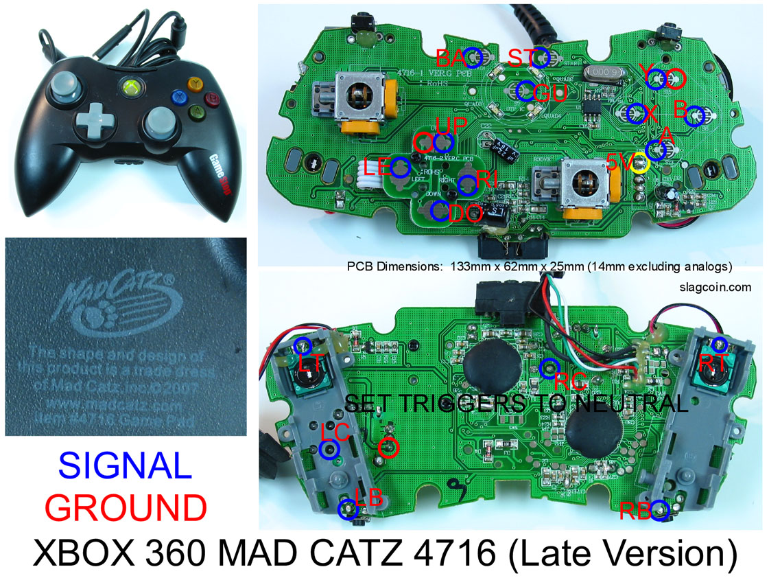
I am working to make a fightstick by modding a madcatz xbox 360 wired controller, one of the newer ones. I have some questions about how the common ground works and the bumper buttons.
What is the optimal starting point for the ground wire that will daisy chain between the cherry switches? What is the optimal ending point? Is there anything else the wire needs to connect to in between?
I am also having a hard time with the small black buttons attached to the l/r bumber buttons. How exactly do I connect to these? Can I use the solder points on the bottom side of the board?
I know these question have probably been asked before and I appreciate your patience. I may just need someone to direct me to the correct post with the info I need. Unfortunately, I surfed this site for over an hour and did not find specific answers to these questions. Probably my fault, I realize.
Thanks!!!
There is no Solvent im aware of to remove the conductive padding. Just scrap it with and insulated scrapper, if you dont own one use an exacto knife.
Yes you can remove the two small pcbs for L and R. just solder to the points provided.
No you dont need to solder anything to the 3.3V connection for a single pad hack.
There is no optimal starting point just use any spot adjacent to a signal for your starting point for the daisey chain.
Yes use the small solder points behind the shoulder buttons just reference the diagram from slagcoin for help.
Any other questions feel free to ask.
I want to use this ps pad but im not sure what series it is. Can someone identify it and let me know the layout please.
http://i298.photobucket.com/albums/mm275/mountaindewfkr/DSC01785.jpg
http://i298.photobucket.com/albums/mm275/mountaindewfkr/DSC01784.jpg
i need your help again 
as i posted before i made a mistake with my pcb (wrong schematic). so i had the triangle button signal cable connect to the ground instead of the signal connector on the pcb. i corrected that / tested it, build everything into my case and tapped the pcb to the top. now it seems like i somehow made a connection between ground and signal on the pcb because the button is permantly pressed without even the button cables connected to the button.
http://tt08.kilu.de/IMG_0560.jpg
http://tt08.kilu.de/IMG_0559.jpg
(triangle connector seems to create that problem)
how can i solve this problem? ;-/
Hi Dexa,
you cold either some measures with a multimeter and test the restistance between singal and ground under question. Without such help you’re “blind”. Then try to desoldier and soldier again. Check twice the wiring.
Hardedge?
Bencao
not sure if i can find a meter here. (ofc hardedge … you can answer there too :razzy: )
ya will try to solder/desolder. ill report back.
right next to SW8 is free soldier point. try to use this one
okay, have a nice evening 
thank you
desoldered the wire -> still always active.
Thanks, this will be my first time doing one of these.
Malaysia ps1 controller-
I have acouple of quick questions before i start.
-Do i have to scrape the stuff just off the spot im gonna be soldering or more?
-When scraping the black stuff off the contact do i stop one i see the gold or do i keep going till its alot more visible and brighter?
-Whats the best size drill bit to use if i want to drill through solder point?
Thanks
OK!!! Big Hurray!!! I finished my arcade stick and it rocks…
The below link is by far the most helpful link I found.
http://omgbbq.com/tfight360.htm
I would suggest testing each button yourself to make sure you know where the ground is. I bought a 2008 Game Stop/Madcatz wired gamepad and it differed from the schematic everyone was showing by a couple of buttons.
Regarding taking advantage of the common ground used in most 360 pads, your daisy chain can start with any arcade button and ends connecting to any of the ground nodes on the pcb.
Finally, I am not sure why more hasn’t been made of the l/r bumper buttons as they are more of pain to solder and figure out. Leave the small black button attached and wire to these buttons from the bottom side of the pcb. It is alright that they don’t look like the other solder nodes on the pcb.
Don’t feel like you need to spend a lot of time or money on the box your sticks will be mounted in. I bought a nice wooden box($1.99) at a thrift store and drilled it out with 1’3/8"($13.50) bit. It’s lovely!
I was able to find local joystick parts on craigslist.
I want to say thanks to everybody who helped me with this. I also would like to encourage others to go ahead and make a stick rather than spending mad cash on something off of ebay or waiting months for retail to become available. I knew nothing about joysticks, electronics or solder Wednesday night when I decided to embark on this project.
Sincerely,
Titanic
I messed up a test point (tp 39) on the back of a microsoft controller for the “A” button and now the A contact on the front does not work. Can anyone give me a hand? Thanks