One final thing, if I do want to solder to the trace, do I need to scrape to reveal the copper there as well?
No Problem
Yes you would have to scrap to reveal the copper trace.
Any idea how deeply I should go (or avoid going in order not to sever the connection)?
Thanks a lot! I’ll give it a try soon
Dang. I just bought an open-box wireless Microsoft controller at Future Shop (Best Buy) for $30CAD ($24 US), got it home, and then found out it was the early version that’s not common ground.
EDIT: I took a look at the controller I had been using with my xBox, and it was common ground! So I just switched the new one with that one, and away we go!
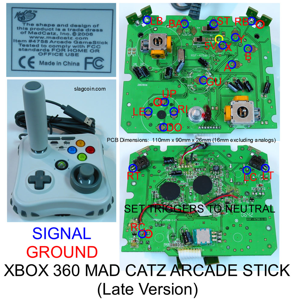
can someone explain to me or direct me to a guide to getting the triggers to work as buttons with resistors. I’ve tried to sift through this thread but there seems to be a mix of playstation/xbox360 posts mixed in with various types of controllers… but anyways most of the posts I did find about triggers was getting them to stay off… which is not what I want to do. The search functions seems to be down, so could anyone give me a hand? RT and LT are labeled… can I just use those contacts if I keep the triggers on the PCB? Thanks
I even tried that. I worded my post poorly. The pad is already wired up with individual wires for grounds. I did find that night that B shared its ground with Y. Im going to look on the board for another spot to solder for the hot side of the B button although I think the issue goes deeper than that.
Just thought I would share this, zombie qpt here on the forums has a soldering service he is offering. He will hack your pad for you for a small fee.
I had him do this for me on an MC360 pad and here are the results…THIS is how a pad hack should look:
http://i156.photobucket.com/albums/t11/parabellum9x19/Arcade/Zombie_qpt_solder_MC360_01.jpg
http://i156.photobucket.com/albums/t11/parabellum9x19/Arcade/Zombie_qpt_solder_MC360_02.jpg
http://i156.photobucket.com/albums/t11/parabellum9x19/Arcade/Zombie_qpt_solder_MC360_03.jpg
http://i156.photobucket.com/albums/t11/parabellum9x19/Arcade/Zombie_qpt_solder_MC360_04.jpg
Okay, I read the last 10 pages and didn’t see anything on the Pelican Afterglow PS3 controllers. Either these have been already deemed no good, or just not discussed. I’m going with the former, but would like to hear what has been discussed about this pcb.
You’re going to have to give a bit more info… The way analog triggers work is the controller reads the voltage of a single pin to determine how hard the trigger is pressed. There’s a pot hooked up to it, as well as ground and high, and when you press the trigger, it shifts the wiper (the pin that the controller reads the voltage from) from high to low, or vice versa. The problem here is some controllers read the trigger as unpressed when it’s voltage is high (this is a good thing, easier to hack) and some read it as unpressed when it’s voltage is low, ie grounded. If you can post what controller you have, we can steer you towards how to hook up the triggers.
I think the general consensus was either get a Cthulhu, or use an official pad for wireless, I haven’t seen much if any discussion about other ps3 pads.
Thanks (and to zombie qpt!) for these pics. Mine won’t be anywhere near that neat but I’m definitely going to steal the ‘glued down away from the actual solders’ idea.
That is standard for good board mods…you need to secure the solder points to prevent fatigue, but you can’t glue over the solder points or FORGET about repairing one if you need to.
Hot glue on another part of the board = success.

Yup. I was just going to leave the glue off altogether but this is the best of both. :tup:
If I desolder the triggers on a MadCatz 360 pad and leave them disconnected, i won’t have any problems with the pcb will I? (they have 3 soldered pins each)
Read this: http://forums.shoryuken.com/showthread.php?t=169203
If you just remove them I believe they register as being on all the time.
The small pcb “tabs” that are located on a Mad Catz retro arcade stick that are used for the buttons can be removed correct? As far as I can tell they just just bring the button signal and the ground signal between each tab pcb (where the button contact is located) and the main pcb. If I remove the tab pcbs it I can just take the signal from the main pcb without any trouble correct?
“Pcb tabs” I speak of are in the top left and top right of the pcb in the top right picture: http://www.slagcoin.com/joystick/pcb_diagrams/360_diagram2.jpg
Thanks for any help in advance.
Correct. It’s suggested that you heat up the solder points with an iron, then use a plier to take the tabs off. It will lower the chance of anything breaking. But yes, the tabs only contain the contact points for RB and LB, as you can see, the triggers use those black plastic bits on the back.
So I got a radio shack multimeter. If I wanted to find the voltage point on my pcb how would I test that? There is + and - leads obviously, the + will go to the point I want to test, and the - would go where? Sorry for the n00b question.
Ground on the pcb.
Ground on the pcb… Although you will most likely be using the continuity check or resistance measurements more often for pad hacking to check for common nets or if you accidently shorted something.