Has anyone hacked this pad sucessfully? I am trying to help out a friend who has this pad. The problem is the B button does not work. Every button on this pad has a seperate ground. All of the other movements and buttons work except the B and the guide button. I’m not worried about the guide as much as the B button. So far I have took the older solder off, put new solder on, put new wires and quick connectors, and changed the switch. All of this and still nothing can get the B button working. Is there anything special that needs to be done to this pad? I’m at a loss and frustrated since I can’t figure out what the problem is.
Anyone know where I could find information on hacking a Sega Genesis 6 button controller?
any tips on soldering to the bumpers of the madcatz late version 360 pad? Seems like it’ll be hard to solder to
People, just don’t buy official 360 controllers, they are such pigs to solder to !
Hacking the various buttons is not difficult, but doing so for the D-pad is a NIGHTMARE (this cannot be stressed enough). The spots are very tiny (sub millimiter size I’d say), the pcb has to be eroded around which facilitates contact between two spots of the pcb which are not meant to be connected !
I spent a LOT of time trying to make a decent 360 with a game controller someone asked me to mod, but I’m going to have to resign (what a waste of time and money) plus I’ll hack an easier to mod 360 pcb like the madcatz retro stick. I’m not going to make a lot of money 
Some china companies sell 360 controllers for a fair price. Has anyone tried them, are they good for hacking ? Madcatz products are nowhere to be found where I live (I have to buy abroad)
Is there a way to shave down the size of the madcatz retro stick?
B and Y share the same ground in that pic, both on the right side of the button… Try a wire from B’s signal on the left to Y’s ground and see if that works.
Does anyone have experience with this MadCatz #8002?
It looks like common ground but can anyone tell if there is a power source on this pcb?
http://img.photobucket.com/albums/v504/tharimrattler/DSCN1982.jpg
http://img.photobucket.com/albums/v504/tharimrattler/DSCN1987.jpg
http://img.photobucket.com/albums/v504/tharimrattler/DSCN1985.jpg
http://img.photobucket.com/albums/v504/tharimrattler/DSCN1986.jpg
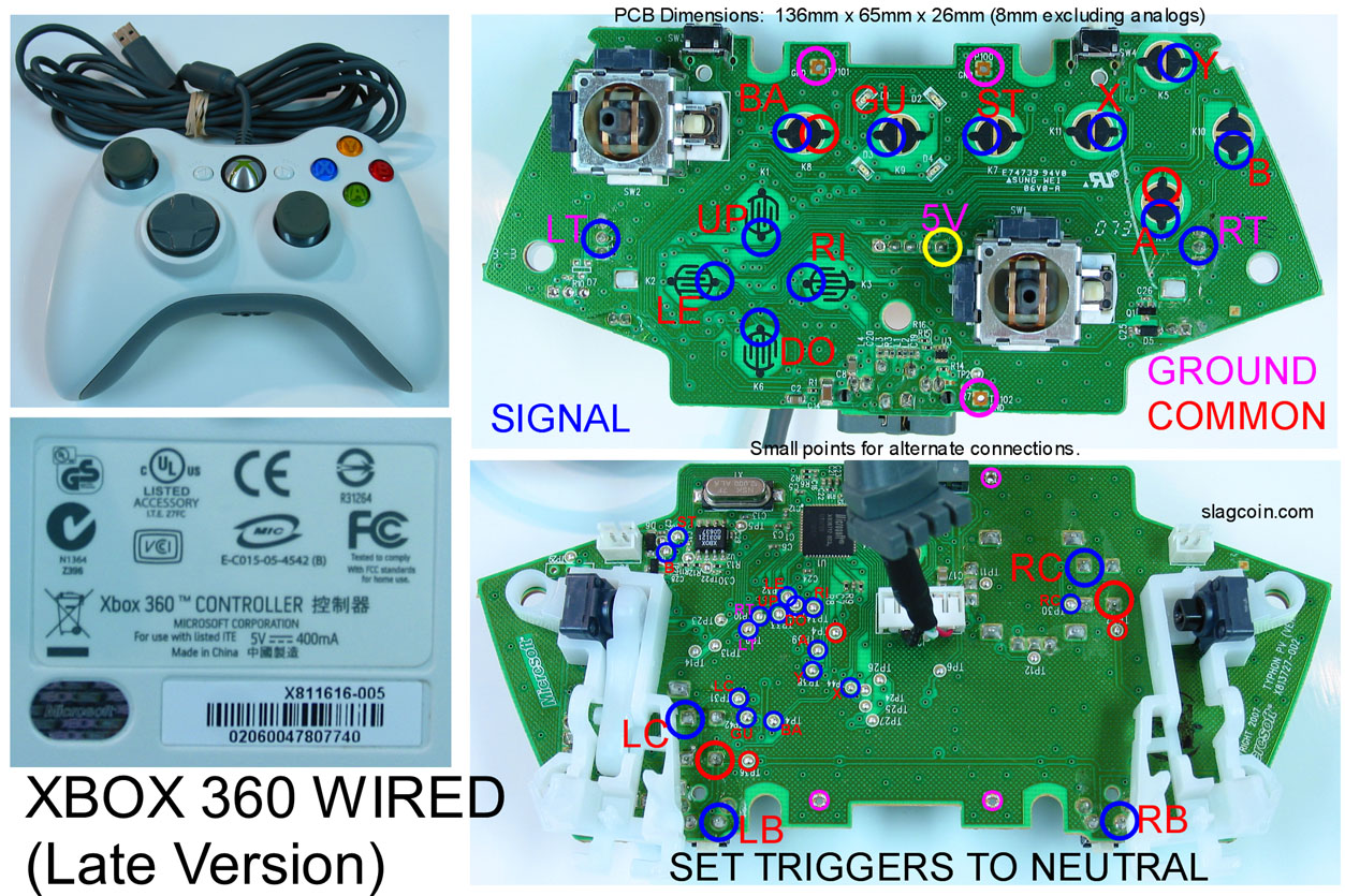
I’m planning to padhack a Microsoft 360 Wired controller.
However I have a the early version (non-common ground) and I’ll have to pick up a new controller from bestbuy or somewhere.
- Are typically all the 360 Wired controllers in the mainstream market, such as Best Buy, the common ground versions (late version)?
and also I have another question:
- Where do I solder the ground wire (to be daisy chained) on slagcoin’s late version diagram?
http://www.slagcoin.com/joystick/pcb_diagrams/360_diagram1.jpg
Is it one of the pink circles? or one of the red circles?
Thank you!
For your ground use any circled in red. Really any spot adjacent from a blue signal can be used as your ground spot to begin your daisey chain.
That is a common ground PCB, you can tell by just following the large traces. To tell where the power source is I would need a multi meter to check. To tell which side is ground and which is signal for each button just follow the large traces to see which one connects all the buttons together(Would be much easier if you had a multimeter to check).
I picked up one of these earlier,
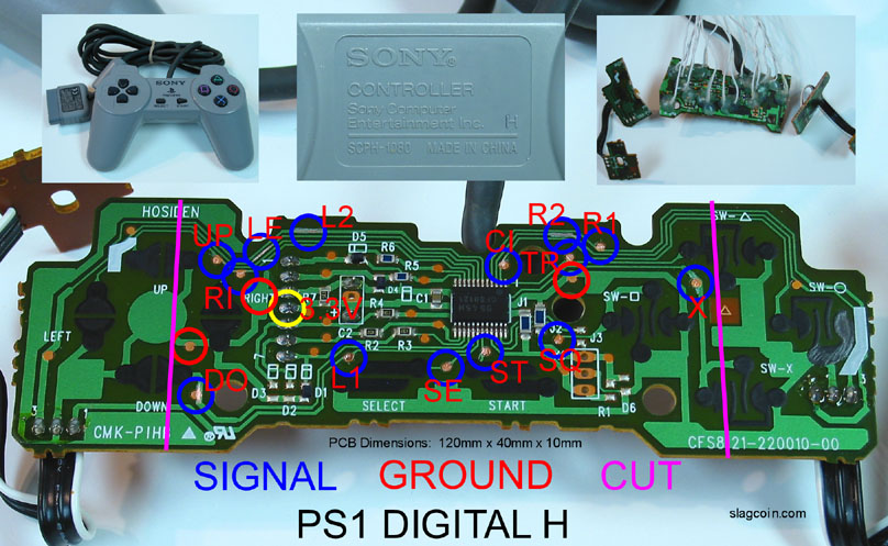
but am really confused about where to solder for the left switch on the digital pad. Am I meant to solder on that tiny tiny pathway circled on the image without the solder touching any of the adjacent pathways? I think that’s beyond my ability if it is indeed the case. In general, I don’t seem to be getting the correct readings with my multimeter that I believe I should be getting, almost as though signal and ground are reversed in the image. Any idea what I’m doing wrong?
Yeah I identified the ground, but how would i find the power if I get a mutimeter? I could use one tomorrow.
I agree it can be difficult to solder to the tiny d-pad points, but if I can suggest to you if your having problems soldering to them, just use the alternate points on the back. The points are larger and have solder on them to begin with. So its really just a matter of tinning your wire then heating it next to the point.
Just a couple tips that I found made my life easier when soldering to the small dpad points on the 360 controller.(learned the hard way almost ruining a controller or two, now its childs play though after some practice)
- Scrap your tiny d-pad spot with an exacto knife
- Tin your wire
- Apply some solder on its own to the tiny spot
- Then place the tinned wire tip over the tinned copper tab from the d-pad
- Heat the top of the tinned tip of the wire and remove the soldering iron
- Apply the hot glue melt to that.
I just finished my wireless 360 stick and soldered to the pads on the pcb… Sure, I nearly destroyed the left-dpad and back buttons in the process, but they still work with some fiddling (soldering directly to the left-dpad’s trace in that case) Just take your time and dont get frustrated while you’re working on it. Its only $35 (amazon) even if you do mess up.
You only need to solder to that trace if you paln on cutting the board down like in that picture in the upper right corner(if you need a small pcb to fit in your case). Its not nessesary, so feel free to just scrap the large contact pads if you more comfortable with that. or use the other small contacts along the traces.
Thanks for that. Some of the points labeled in the diagram don’t function correctly for me still though. I’ve mapped everything out with my meter and there are some discrepancies. As for scraping away the black material, how do you recommend I go about doing that?
Really you would want to use an insulated scrapper. But using an exacto knife would be fine.
The black stuff seems to be conductive, but I take it that it doesn’t take solder?
No solder wont take to it, you will need to scrap down to the copper contacts.
Thanks Shadow, you’ve been very helpful.