Then when the button is pressed, you are connecting Vin to Gnd through a 100 ohm resistor. I=V/R, so I = 5v/100= 50mA of current each, 100mA of current if both buttons are pressed. This along is the very top of the maximum guaranteed current available in the USB spec, so the pad itself and any LEDs would push it over the top.
I’m glad if it works for now, but you really really should consider swapping those out for higher value resistors.
If you want to test the resistance of a pot, remove the pot from the board and then measure the two outermost legs, and not the inner wiper leg. If you test connected on the pad itself, you’ll get a bad result since it’s in parallel with 5 other identical pots.
EDIT: Whoops, reading comprehension fail. So you’re using 10mA when they’re pressed. Still a bit high though.
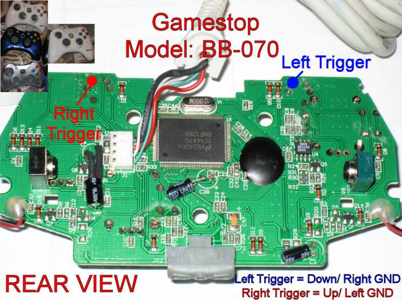
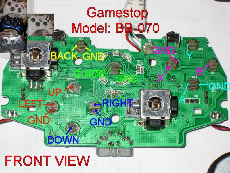
Where I work I have access to old video game accessories and have been looking for 360 periphrials to hack for a stick. So far I have taken apart a 360 gamestop controller which I tried hacking but messed up on the triggers. So I then used a DDR pad & found it only had 4 buttons x,y,a, & B, which I guess I could use for soul caliber or even tekken but need 6. Today I took apart a rockband drum set & found it had 4 buttons on the face & also had the 4 drum pads hooked up with wires coming from the pcb. Does anyone have any experience or heard of someone using the drum set pcb to pad hack? Any info would be great, I will also mess around with it & post anything I find.
Are all wired Microsoft 360 controllers the same? Do any of them have common grounds? I have one from Gogamer that I wouldn’t mind sacrificing to build a stick.
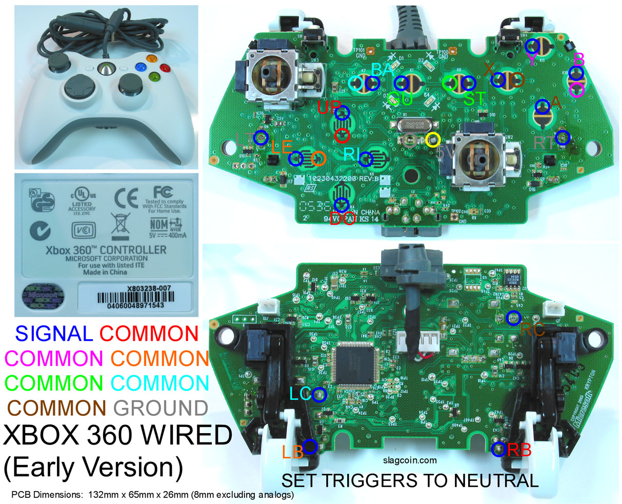
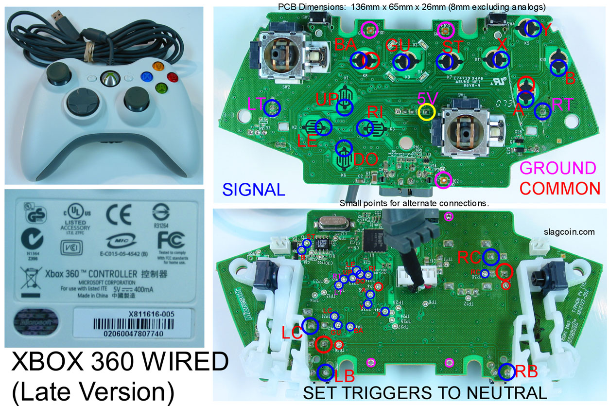
There are two different wired Microsoft controllers, one is common ground and the other is a matrix. Take a look at the sticker on the back, and compare to these pics, there’s a few differences, most notably the icons.The first is a matrix, the second is common ground:
Thanks for the quick reply. Mine looks like neither. Well, it looks more like the second one than the first. I wonder if it’s some bizarre bootleg or something, but it’s worked just fine so far. What do you think?
Also, anyone up for hacking this for me? I can send, along with the controller, wire, terminal blocks, fork ends, quick disconnects for both sizes. I will pay some, too, but hopefully not a lot.
I’m new and trying to learn how to do all this. It’s been years since I soldered and never did anything this serious. I’m assuming that for the common cround ones, the pink circles are the ground, and it doesn’t matter if the ground for the buttons all go to the same ones. As opposed to the matrix ones where I have to set the ground to the corrisponding button ground. Is that right?
I’m confused about why there are so many different colors for grounds… But anyway, yes, common ground means that you only have to solder 1 wire to the PCB to cover all the grounds, then you daisy chain them to all the buttons/joystick microswitches. You still need to solder 1 wire to the PCB for every button though. If it’s not common ground, you have to solder 2 wires for every button. So having a common ground eliminates almost half the soldering work and also uses less spots if you are using terminal blocks.
Edit: Oh, I guess in the “matrix” one, certain clusters of button share a ground, but its not 100% common ground?
I’m going to say that’s probably a common ground controller.
Yep, that pretty much sums it up. On the matrix ones, or controllers where the common point isn’t true ground but all buttons share a common, you’ll find the color of each buttons’ label matches the common it should use. With a matrix, you’ll frequently see 2-3 buttons that can be on the same chain, and in the case of the 360 common ground controllers, all of the buttons are on the same common, but it’s not a true ground, so the triggers have to be on true ground, which is a different color.
I keep getting the wait for 1029381029517206 seconds until searching so thought I would just ask my question directly. I currently have a joystick that works pretty well, but I will be moving to a new case and wanted to make some simple additions.
With the Late Microsoft 360 Wired controller, how can I extend the headset jack so I can use the headset while playing?
Any 2.5mm extension will work, there were short ones shipped with Rockband, but there’s nothing special about them. Just remember that if you use an extension, the 360 will think you always have a headset plugged in, so you won’t be able to use a wireless headset without opening the stick and unplugging it.
ok thanks. So what’s that thing about setting the triggers to neutral about? I assume it has to do with the pressure sensitivity, but don’t want to start soldering without knowing. And if so, why do I not have to worry about the pressure sensitivity of the other buttons as well.
Could someone also explain the LC and RC? And in the matrix PCB, what are the yellow and grey unnamed circles in the middle of the controller?
Yellow is 5v, gray is ground. LC/RC are when you click in the left or right thumbstick, not something you should worry about. As for the triggers, if you’re not going to use LT/RT, you don’t really need to worry about it, just leave the pots on and position them to where they’re not pressed after you take all of the plastic trigger hardware off. If you are going to use them, you’ll need a couple of resistors, there’s a ton of info on it.
The headset is mono, and the mic signal is carried instead of a second channel, so you’d just plug the extension into where the mic normally plugs in, and plug the headset into the extension. If you have an older headset with the misc connectors on it, you can just ignore those, it still works fine.
(edit)
You can see in this picture that the only thing with a wire going anywhere inside the original headset is the 2.5mm jack, the connectors on either side aren’t hooked to anything.
Actually im getting the left and right bumper commands where the left and right triggers are marked? I think that im going crazy or this diagram is wrong?? hmm
Yep, the diagram is wrong, those are the left and right bumpers. I’ve circled the trigger connection points in orange here, but you’ll need to figure out whether they’re low or high when pressed, to know whether or not you’ll need to use a transistor setup.
Do you mean the black plastic pieces for the triggers (LT + RT), guide button and the bigger haousing of the left analog stick?
I do have the same pcb and I am hesitant to remove the black plastic. It looks as if it is fixed with the small black pins to the pcb. Do these need to be drilled out? Or ist that the same thing you are referring to and they are also only fixed by solder? Is it really just “pliers + brute force”?
Can you point me in the right direction here? I’m afraid that I’ll rip the traces off and the retro arcade sticks are not easily available here in europe.
