Thanks for the replies and clarifications. 
Going to try a couple of other sources tonight, and hope for better luck. Worst case, I’ll trek over to the Walmart at some point this weekend to see if I can’t find a Joytech Neo.
Thanks for the replies and clarifications.
Going to try a couple of other sources tonight, and hope for better luck. Worst case, I’ll trek over to the Walmart at some point this weekend to see if I can’t find a Joytech Neo.
Thanks for the reply. I have used the exact same ground as in the picture on the slagcoin website, the ground in pink. So, do you think the only way to get it working is by removing the pots and adding a 10k resistor?
Also, how do i get the sync button working? i’ve attached this also, exactly like in the image but this don’t work too.
thnaks
The sync button should work just like any other digital button, there’s nothing special about it and there’s no need to remove the switch. As for the triggers, I was fairly sure that you had to remove the pots and use a resistor, I’ve just always started out doing it that way so hadn’t tested myself.
Thanks for the help, I picked up the cheapest digital multimeter I could find and it’s been very useful. So far I’ve been able to test one of the trigger points I thought I may of ripped up to find that its ok and promptly glued that fucker down. Was also able to test a point that was pretty close to being shorted but looked fine. It gave a reading, albeit a very high one, so I sorted that out too. Thanks again.
Any takers?
thanks again. When i get some time, i’ll remove the pots and give that a go, see what happens. Don’t know why but the sync button didn’t work for me. I’ll try again when i do LT and RT.
Ive just been randomly testing a few points on an official xbox 360 matrix pcb and noticed that quite a lot of points are coming back with 0 resistance. For example:

Is this normal or have I screwed something up?
With the Madcatz reto Gamestick, what’s the best way to remove those tabs on the pcb that the LB and RB were attached to?
Your trusty pliers will do the job. They’ll snap right off with a little bit of force.
I was working on my retro gamestick the other day and managed to remove the slider potentiometer thing and the 2 analog sticks. It was damn frustrating taking those sticks out. Also managed to rip the middle contact point off on the right trigger but luckily there was another point I could solder to. Just need to wait for my parts to come in from LL to start modding.
The two points you have red arrows to aren’t associated with any of the buttons, and there’s no map of what they connect to, so I don’t have any way of saying if they should be connected or not offhand… Still, unless you were specifically messing with them, I’m going to say it’s fine. These are fairly complicated controllers, there are plenty of points that are interconnected.
Turns out they are only held in place by solder. I was removing old solder form the contact point on one just fell off.
The middle tab come off of one of my triggers to. I just scraped and attached next to it.
should be a 3.3v
looking at the pcb with the green side up it should be 5th pin down from where the psx cord is connected.
i’m just going off memory but you’ll know it’s the one because it has a thick line to the right of the pin tracing it back to the chip.
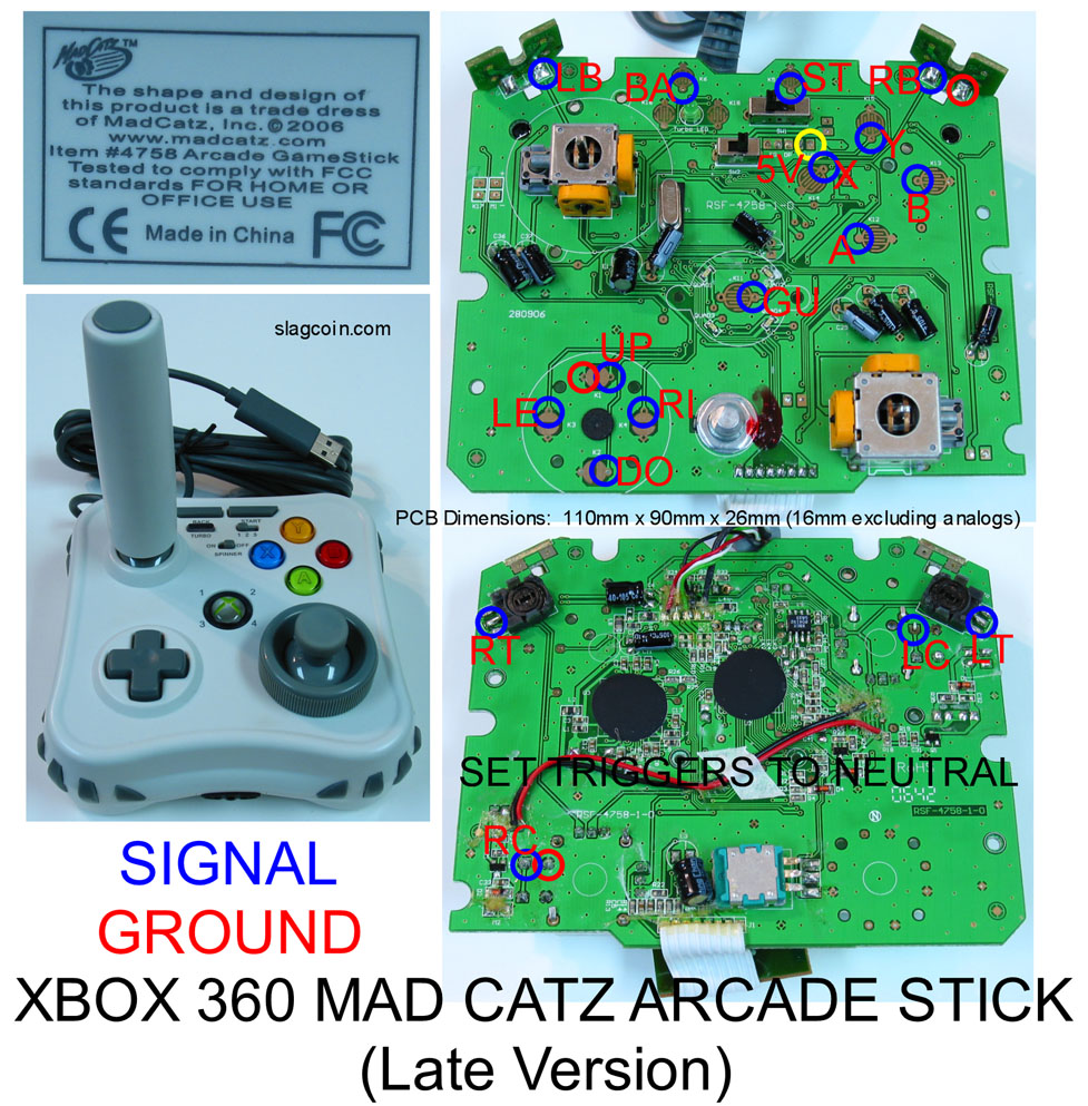
So I posted earlier for help with my madcatz late 360 pcb I soldered wires to the Y and UP points posted here: http://slagcoin.com/joystick/pcb_diagrams/360_diagram3.jpg
I made a daisy chain from the wire I soldered at the Y point and the buttons work perfect, but the stick didn’t work at all. I’m using a sanwa JLF with a 5-pin but the 5-pin is a seimitsu 5-pin and I connected it to my pcb using a wire terminal(Including the ground wire from the up point) but the stick didn’t work. Help would be much appreciated cause I REALLY wanna play SF4 on stick cause I don’t see my JLW coming from lizard lick for a while now:sad: Thanks.
Can you please post a photograph? I’m not sure what you mean.
Is it not taking any of the directions? On my PS2 stick, I did not have a 5-pin female connector available so I had to solder DIRECTLY onto the 5-pins on the microswitch board. When I connected to the PCB, it was only reading two directions completely wrong. So I took my stock SE stick apart and examined the microswitch board. I found out which pin corresponded to what, re-attached wires to PCB, and it worked great! I had gotten some info about the 5-pins and which gives signal to what, but it didn’t apply to the SE stock stick. The reason I’m explaining this is you might have mixed up the wires, therefore the signal isn’t going through. Make sure your daisy chain connects to your ground wire on your 5-pin female connector.
As wished by Drachenherz :razz: here`s a pic of the pad-hack. Its an Big-Ben Xbox360 PCB.
http://www.pic-upload.de/13.03.09/ccl5b6.jpg
The Trigger-Buttons arent soldered yet, cause of a lack of wires :rolleyes:
On Saturday im going to buy a new wire-set and finish the job.
i’m going to remove the triggers and pots tomorrow and wanted to know whether i could use, two 4.7k resistors instead of, one 10k resistor on LT and RT?
thanks
Sure, but you can use just one 4.7k if you like. The resistor values arent too important, as long they’re rather high, say over 2k.
thanks.
I used 1k resistors on mine since the pots only registered 100 ohms (for both Vin to wiper and from wiper to Gnd). This is for the madcatz pad though.