Could anyone suggest the easiest PS3 pcb to hack? Also, is there a link to a guide on doing so?
my FS3 PCB is a little screwed and I’m having trouble figuring out where to solder now, some of the traces are messed up and I’m lost. Especially as the stock hori uses no wires.
This is something i’ve wanted to know as well. Is it as simples as just touching two points on the board? Are there any special settings my multimeter should have?
Well, if you have a DS3 laying around that you don’t need, go with that, they’re fairly easy to hack, though they aren’t common ground. If you have to go buy another one, though, the Cthulhu should be a good alternative, especially since if you’re comfortable soldering you can buy a kit for half the price of the assembled one.
The most common thing you’ll be using it for is testing for continuity, and yep, you’ll just be touching two points on the board. Any digital multimeter will have a setting for it, I’ve never messed with an analog multimeter so I couldn’t give you any first-hand experience there. The icon should look like a triangle with a line through the middle, and most also have a small three-wave speaker icon next to it, as they beep if you’ve got low resistance.
If you have a pcb that isn’t mapped out, you can map it out yourself fairly easy. Start with any button, check one side of the contact against both sides of all other buttons and the dpad. If it has 0 resistance to a contact on every button, you have the ground for the button you’re testing, and it’s a common ground. If it has 0 resistance to only a few buttons, 1-2 generally, you have the ground for the button you’re testing, and your controller isn’t common ground. If it doesn’t match any other connection, you have the signal for that button, switch to the other contact and check if it’s common ground or not. If it’s not a common ground, make sure to map out which buttons share a common.
If you’re worried about a short, the same setting is what you use, just touch each probe to the two things you’re worried about, and 0 resistance means yes, you’ve got a short.
I have a DS3 ready to hack, but I don’t know what the hell I’m doing. I have no stick, and they’re totally impossible to find right now…Also I refuse to play on a pad. Ew, no no no.
Can anyone link me to an uber-scrub friendly PS3 hacking tut? Or any sort of easy-to understand map of the pcb? Thanks a bunch.
Then, there’s the hori PCB I have with dead “tracers” whatever that means. I know I’m meant to follow the path up, but where? I have no idea where I solder if the tracer is damaged. Is there a decent map of where I can and cannot solder for each button?
I am going crazy trying to get a damn stick to work, good or bad. Curses.
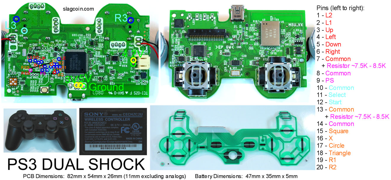
See the pins in the connector that the button plastic came out of? From left to right they’re labeled on the side of that pic. You run one wire from each of the signals to the button or switch for that, and then you chain a common around to the other side of each button and switch that the color matches. The entire dpad and L1/L2 are on the same common, Select and Start are on their own common, your four face buttons and R1/R2 are on a common, and the PS button has it’s own common. You also need two 7.5k to 8.5k ohm resistors, which you need to use to connect pin 7 to 8, and 13 to 14.
Okay, searches on this thread and this forum aren’t yielding me much. So:
Does anyone have any idea if this purchase would net me a common ground PCB? I’m seeing a lot of conflicting information, some of which suggests that the only Mad Catz control w/ a common ground PCB was re-branded by Gamestop. Unfortunately, the only Gamestop branded controls in stores – at least the three by me – are a much newer, non-Mad Catz model.
Now he sent me a PM regarding how to make the ground wire for the pcb by making a daisy chain, This is it:
Take a thin gauge wire (can be from any old wire that you do not need anymore, ex: telephone cable, ethernet cable, ide ribbon cable.) Use an exacto knife to expose the copper for an inch, every 5 inches along the wire.
It should look like this:
=====—=====—=====—=====
The button and joystick terminals for ground have little holes in them (sanwa, happ, seimitsu, all do…) stick this wire in the hole and loop it in such a way that the exposed section of our wire wraps around the terminal… use electrical tape to wrap this terminal with our looping ground wire around it and repeat with the next exposed section of the wire on the next ground terminal.
You need to connect the grounds for every button and joystick microswitch you have, just connect any of the two terminals (three if you are using happs) on every button to the ones on every other button, and finally use the ground wire with the quick disconnect on it to connect one of these terminals to your PCB. Just slide that onto any of the ones you chained to the rest.
I’m a noob when it come to PCBs and soldering so I really don’t understand this so my questions are where do I put the ground on the PCB do i solder it or just use a QD and place it on the PCB and Is there anyway I can use a JLF without the scraping mod and use a wire terminal instead?
I haven’t seen anything one way or the other on that specific pad, so I wouldn’t order it online. My advice is to pick up a Joytech Neo SE from Walmart, they’re ~$25, and the “new” ones are a rebadged madcatz with a common ground. I believe ~1-2 years ago the NeoSE’s weren’t common ground, but every one I’ve picked up in quite a while has been. You can peek in the package to double check, the common ground will say “M/N: 4716” on the back sticker.
You have a common ground pcb, so you don’t need to do any scraping to the JLF to use it. I’m assuming he soldered one ground wire somewhere to the pcb, so you shouldn’t need to solder to the pcb itself. You basically just need that ground wire to touch one of your buttons, and then run that with another wire to every other button in your stick, as well as the black wire of your joystick harness.
The upper portion where the star, select, home and stuff are, the button there are attached to a small pcb and attached to the main with a ribbon cable that hits all the contact and the ground point there. If I want to wire it so those buttons work with a 360 pcb i’m installing would I have to disconnect that ground point and then conncet it up with the rest. My goal would be to get the signal to have to go through my wiring and not the stock circuit path. I’m assuming if I left it as is the the current would take the path of least resistance and my 360 button presses wouldn’t be registered at all.
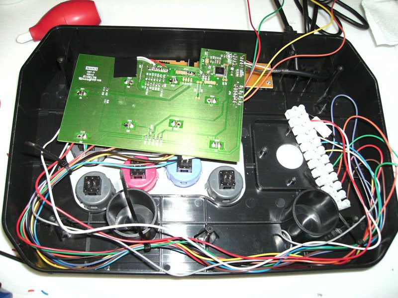
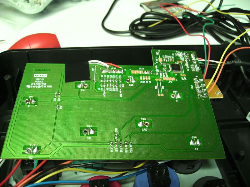
Here’s what I have thus far. I haven’t wired up the 360 pad yet but it’ll plug into the same side as the FS3 PCB.
Edit: You know, I’ve been thinking about it some more and I’m not really sure now. The whole system will be common ground so I guess it doesn’t really matter where the circuit connects to ground at. I’m really unsure.
You have a common ground pcb, so you don’t need to do any scraping to the JLF to use it. I’m assuming he soldered one ground wire somewhere to the pcb, so you shouldn’t need to solder to the pcb itself. You basically just need that ground wire to touch one of your buttons, and then run that with another wire to every other button in your stick, as well as the black wire of your joystick harness.
[/quote]
Nope he didn’t soldered any ground wire at all just the wires for the buttons and stick.
Ugh. I was afraid of that. It really seems as if the information available online is starting to fall behind the currently available product curve. Unfortunately, contacting the third-party vendors selling that pad on Amazon has yielded exactly zero details regarding item # and date of manufacturing.
This pad is the one Gamestop is currently stocking. Can’t find anything one way or another on it online. Too new? Too shitty? Both? Bueller?
That’s crazy. Are you sure there is not ONE extra wire that doesn’t connect to ANY button? That would be your ground.
What he means by this “===–===–===–” is to have a wire’s copper exposed whatever measurements he asked. Those points are going to make contact with the little metal sticks coming out of the buttons. And all of them have holes where you can put the wire through.
I’m assuming that’s what he means. The copper will be touching the metal plates, therefore being able to send the signal.
I’m assuming there is one extra wire with a quick disconnect you can attach to one of your buttons. One button will have two quick disconnect wires going to it. That’s where you can start your chain from because it’ll have the ground signal going there. Then just take the wire and run it through the rest of the metal plates on your buttons/joystick.
Nope no extra wire just the basic 6 buttons and up,down,left and right. That’s why I was confused but I can have a friend of mine solder a wire to the ground on the PCB then all I have to do is make a daisy chain from there and connect the black ground wire from my JLF. Also does it matter that I’m using a seimitsu 5 pin connector? Thanks for all your help!
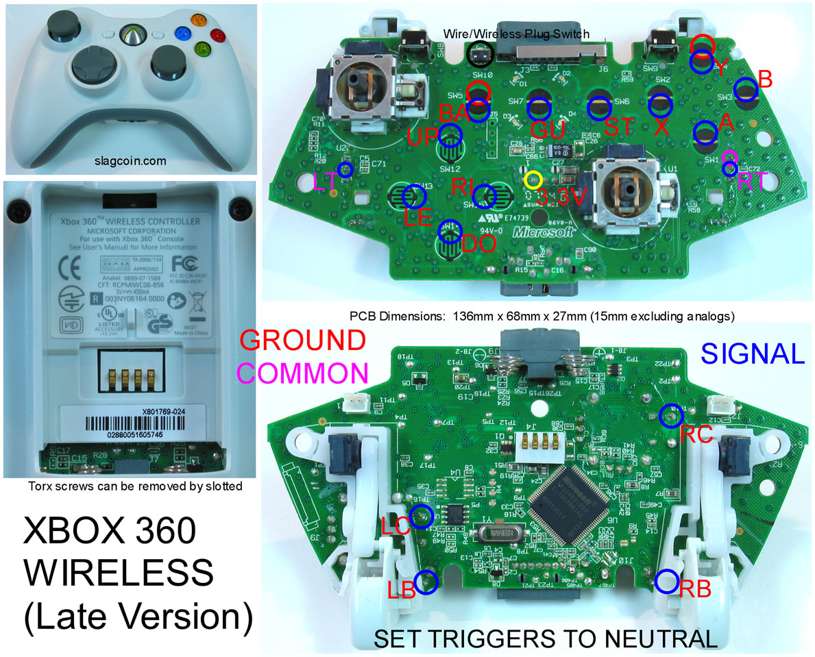
right guys, i have connected the RT and LT points exactly the same way as in here, http://www.slagcoin.com/joystick/pcb_diagrams/360_diagram7.jpg and they don’t work. All other buttons work fine. I have NOT removed the triggers or the pots but still having this problem, please help.
That seems counter-intuitive, I thought the point of buying a pre-hacked pcb was so that you didn’t have to solder to the pcb, in the event that you’re the kind of person likely to damage it. On the plus side, the pcb he used is really easy to solder to, just pick any of the opposite halves of the face buttons or dpad, whatever happens to look easiest for you.
Both… Those aren’t Madcatz at all, and not common ground. Weird that your gamestop only carries those, my local one carries both those and the rebranded madcatz.
Well, first thing, you’re not using the same ground on LT/RT that you did on all of the other buttons, right? They’re not on the same common, so if you just connected them to the chain that would be one reason they don’t work. Also, I’ve never tried to do the triggers without removing the pots, you may actually need to remove the pots and use a resistor as well.

 Those aren’t Madcatz at all, and not common ground.
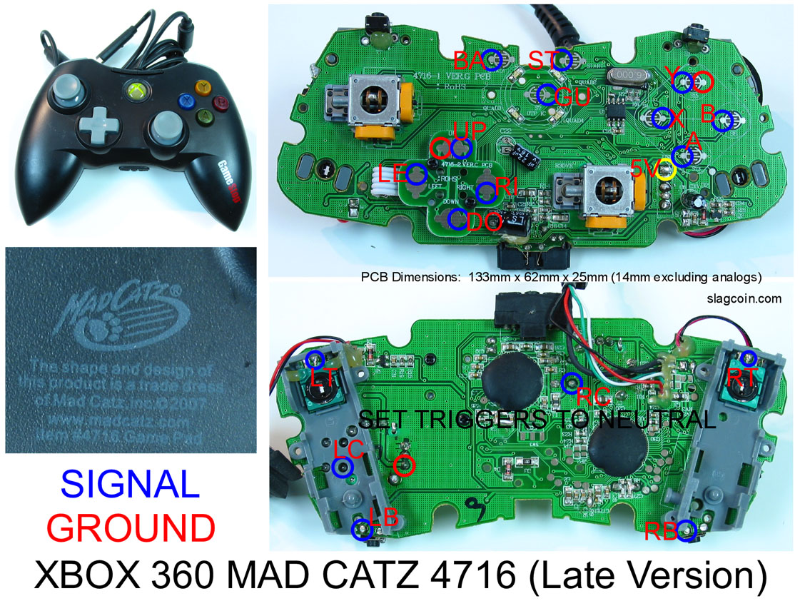