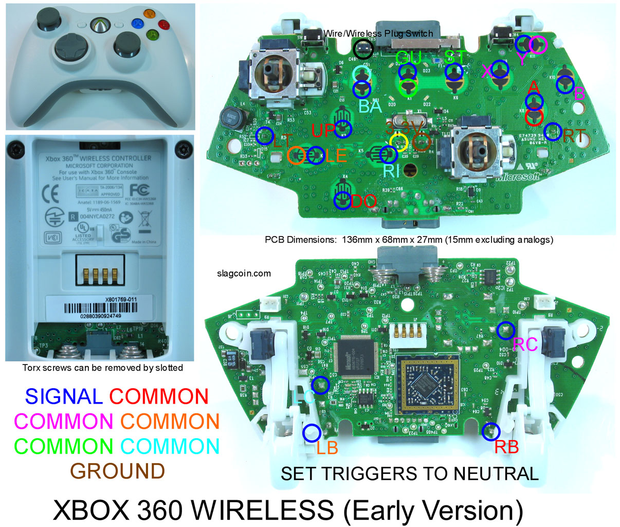
The center pin is the signal, and the topmost pin in that pic is the ground. It’s a true ground and can’t be used for anything other than analog inputs, but you can chain the ground to the pushbuttons for LT and RT, so on the board you only need 3 wires and two resistors for the triggers. Make sure your signal wire is like that picture, on the side of the resistor closer to the middle pin, not on the side connected to the power pin.
Oh okay… that cleared things up. I’m still a scrub at all this DIY stuff (actually my first soldering/carpentry/circuitry/etc project). So how is the resistor connected to the board? Do you just put it through and twist it at the back or do you have to solder it somewhere (this might be a stupid question)?
I’m just trying to gather all the information I can before I start doing anything. I’m actually still waiting for my parts to come and only have a frame build for my box.
Thanks for the help so far.
You’ll need to solder it, push the leg completely through the hole, solder it on the back side, and then trim the leg short after you solder it.
Does anyone have any info on the joytech neo se advanced pad for the 360? Does it have the one common ground? Cant find any info anywhere.
EDIT: Just found info saying some are and some arent. Is there anyway to tell the difference in the models? Also is there a wiring diagram anywhere?
Well I figure what the problem was, I needed to configure the buttons via the Game, I wired all the buttons and after entering the match, I configured all the buttons, and now it works Perfect!!!
I really don’t know why I have to configure them, so if anyone know sbaout it, I would like to hear the answer, but at least, my Arcade controller works Perfectly!!! Thanks!!:woot:
I believe the newer ones are all common ground, much like the madcatz, as they are just a rebadged version of that controller, and even share the same model number. The PCB is slightly different, but it’s very easy to figure out what to solder where. If you REALLY need a diagram, I’ll try to throw one together later.
Note that the triggers are the “hard to hack” triggers, so if you want LT and RT, you’ll need 2 NPN transistors and 4 ~10k resistors. Personally, I prefer a six-button layout, so I just used ABXY and LB/RB.
(edit)
Now that I think about it, the model number was different on the one that I saw pictures of that wasn’t common ground. On the back sticker, the common ground should say “M/N: 4617”, and the other had a longer model number that I forget offhand.
Thanks, think i’ll go try and get one and open it up 
Good luck I grabbed one of the dark gray ones from walmart around the SF4 launch, and had no problems with it. I took pics of the pcb, but never bothered to make a diagram, but if you have good pics when you get one, go ahead and post those, my camera is ancient and awful.
I will do if I can get it. For some reason 3rd party controllers are super hard to get hold of in the UK
Hey guys, I’m building my first stick for use with multiple systems, and from what I understand using the PCB from a PS1 controller is the best way to go. Most of all the custom sticks I’ve seen online use the original digital pad w/o analog sticks. Now i have one digital pad lying around, but I also have 4 Dual Shock 1’s. What I was wondering is, If I were to remove the Analog sticks and their PCB, what will that do to the stick? From what I understand, it’ll cause the variable resistors to read them as a diagonal, is that correct? And how might I go about causing it to not do that, like where would I need to put non-variable resistors and such? Thank you.
I’m having real trouble desoldering the xbox triggers, the solder just doesn’t want to melt. Is my 15w iron too weak or am I doing something wrong?
Make sure the iron is fully heated and the tip is tinned & not oxidized.

Hey, so you’re saying I can’t just wire signals to RT and LT joints and ground it to one of the pink grounds with the triggers still intact? I’m not sure what works and what doesn’t… but I’m just trying to reduce my workload so there’s less chance of my screwing up.
I’m pretty sure I can do the resistor method… but this just seems easier if it works.
Well folks, I think it’s official… my wireless pad is pooched.
It’s really funny… when I take my supposed “guide button” and connect the ground and the signal together, nothing happens.
If I do the same thing with “Start” it flashes the green LEDs in the middle, effectively attempting to turn the controller on. However, they never stop flashing, and I cannot get it to sync with the xbox.
Halp?
Honestly, I don’t know. I’ve never tried to do it leaving the pots in place, and I don’t have an official controller in front of me to toy with. Try it real quick, it’ll take 2 minutes tops to solder two wires together, hook it up to the pc, and test if they press the trigger when shorted or not.
Right I got the triggers off (thanks Exodus) but I think i
i may have damaged the contacts in the process…

Sorry for the shitty image quality but its all ive got. Anyway, as you may be able to see i think i ripped the contacts up, all thats left is some brown rings. Am i right in assuming that this is going to cause me problems?
The other side of the board is fine if that makes any difference.
oh gawd, I did that ALOT on my pad, with my radio-shack special soldering iron… big POS.
If you lost the little copper rings, i think there’s still hope; you have to find a trace somewhere and get some solder on it.
Yeah the copper rings are gone. At least its good to know it might not be completely screwed…
Anyway I’ve sorted my previous problem (I say sorted I just opened up another pad and took more care this time…).
However, quick question. On this image the ground for the triggers is in the middle of the pad is this just an alternate point to the one in this thread (Im assuming the top point in the ground in that picture)? Or am i missing something?
Just posting back as its been a little while since i asked.
But i have now finished all of the soldering on my Later Version Wired 360 controller. I used the back solder points for all of it. I just couldnt get those front pads to work after scraping the black crap off, just wasnt having any of it!
Anyhow, its all tested and working, apart from the guide button, wasnt recognized in windows and theres no xbox where i am right now, but it looks ok 
Anyhow, tomorrow the glue will have set on my frame and i can get back to work…
Thanks to Toodles, bakageta and outk@st. you guys are real Stars!
Good Luck to everyone else attempting this (and if you have a steady hand use the back solder points!)