You keep using that word. I do not think it means what you think it means.
ok, i think i get it now. All the diffierent colours represent which point shares which common ground. So, if i got a late version official xbox 360 controller, i could just use the one common ground for all buttons and the joystick and that should work fine? Also, you mentioned about cutting traces from JLF board. I have a Sanwa JLF-TP-8YT joystick, would i need to cut any traces off this?
thanks
You would be much better off getting yourself a newer controller to hack. The JLF pcb has 1 ground for all 4 directions… if you use an old style controller PCB, you will have to sever this common connection on the JLF PCB in order to properly ground the different directions.
so…
- Buy late model controller
- Wire it up easy-peasy
3.??? - Profit
thanks, i’ll get a new controller tomorrow.
Jesus Christ I cant seem to find a Common ground mad katz pad any where. Every Eb games/ game stop I called only have the one i posted the pic for before. Any one know where in the toronto Area I can find a common ground mad katz pad?
If not then I guess im gonna have to use the official controller.
How do I know if its a late or early model with out opening it up?
Also the solder points on the d-pad look really small and might be tough to solder to on the official controller.
I dont think you can
any one have any advice?
you can tell which one it is by looking at the sticker on the back.
hit up slagcoin and check out the early and late models, you can tell the difference.
Madcatz 4716 - 2008 Model
Hey guys, I bought a new Madcatz 4716 controller from Ebgames Canada and the PCB does not look like the one from Slagcoin’s. I took 2 pictures, front and back; and mapped out the points for all. This is a common ground controller.
I still need some guidance on what is what for LT, RT and confirmation on LC and RC. I’m not 100% sure on LC and RC but I do know that 2 points are always ground which is why I mapped it the way it is. When it’s fully pressed, all 4 points are ground.
With the LC and RC, if you don’t desolder the switches you’re fine using either signal, you don’t need to use both. I’m confused on your triggers though… You mark two pins as ground on LT, but only one on RT, which can’t be true. Either the middle pin is ground when not pressed and high when pressed on both, or the middle pin is high when not pressed and grounded when pressed. Can you poke around more?
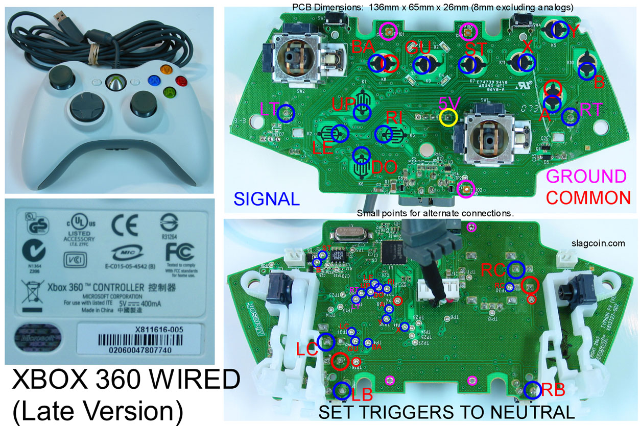
Does anyone have a close up shot of how they soldered LB, RB, LT and RT on a newer style 360 Wired pad?
Heres my pad:http://www.slagcoin.com/joystick/pcb_diagrams/360_diagram1.jpg
Thank you in advance, just having some trouble with those 4 buttons…
Ok what if I don’t want to use the triggers? Do I just leave them alone?
Thank you! it all makes sense now, I didn’t know your suppose to twist those switches, I’ve been pushing it all this times lol. I’ll edit my post with the new back picture.
If you don’t want to use the triggers, just turn the pots so they’re not pressed, maybe hot glue them in place so they can’t move, and ignore them. I prefer a six button stick anyway, so it makes it very simple.
PS2 to PS3 adapter (ebay)
Hello, I would really appreciate if anyone was able to verify the legitimacy of this product, IDK it just seems damn cheap.
I was wonder if this hackable
http://i42.photobucket.com/albums/e339/Sharyakugan/DSC04929a.jpg
this is from my broken PS1 Joytech dance pad.
That looks to be insanely easy to hack, common ground and blatantly labeled.
jeez where could i find one of those, its almost criminal how well laid out it is
Edit: also mags thats the same 9.99 adapter you find at radioshack
Can anyone point me towards instructions on using a multimeter to identify which wires are which inside a controller cord?
Er, do you just mean which wire on a cord corresponds to what pin on the end of the plug? You just want to set your multimeter to check continuity, it should be an icon like this:
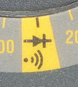
Then, just touch one probe to the pin you want to map, then touch the other probe to wires until you fine one with 0 resistance, which should make your multimeter beep. It doesn’t matter which probe you use for which.
Ok one last question before I go out and buy this pad
its mark with 2 differnt spots for the common ground, so does that mean I just choose eitehr to use?