Ah, I tend to order from Akihabarashop.jp, and they sell the JLF without the plate. I don’t know if LizardLick stocks them. The shipping from Japan will offset anything you’d save, so I wouldn’t worry about it too much. Just take it easy, and if nothing else, drill the heads out on the screws after you mangle them, they’re very soft metal and it shouldn’t be a problem. You won’t be mounting the JLF using those holes, so if you can just get the plate off and the screw flush with the top, that works.
Yea, I emailed lizlick and they were kind enough to reply. Said he would try and remove the plate for me since I expressed my concern about difficulty removing it and he probably has more experience and tools.
I was wondering if i could use a jlf or ls style stick on a non common ground pcb? I was reading and a few people where saying you couldnt cuz the jlf uses common ground. Ive looked for diagrams but may be missing something. Any help would be appreciated!
With the JLF, you can either just remove the microswitch pcb and replace with microswitches, or cut the traces on the microswitch pcb so that the grounds are no longer common.
That sucks! Ill just use my Eurostick i guess. I thought you may be able to wire all d pad grounds to one ground and use the jlf without any cutting…guess not. Thanks tho hopfully there is an easier way out there.
That is already fairly easy. My DC agetec was common ground and the pcb I bought happened to not be common ground.
I just cut the traces to separate 3 of the grounds. the “common ground” wire was ground for one, then sloppily soldered 3 more wires for the other grounds. My first time doing any such thing and took only 8 minutes or so.
That sounds like the ticket. Is there any pics of cutting the traces? I actually have an extra jlf pcb. Thanks guys!!
I have this stick, and when soldering wires to the pcb the wire seems to slip off, and not want to stick at all. Is there anything special I should be doing to solder it on there?
Make sure you’re actually heating the pad, not just touching hot solder to it. If you properly heat the pad, solder should melt on a nearby section of the pad and stick to it just fine.
Tharimrattler I had a few issues with solder sticking to that pad too. You can add some soldering flux to make things a little easier.
alangee, Still looks infinitely better than mine. Id just tin the soldering iron, then tin it some more. Then apply a lil more. Blow the smoke away (first time didnt and had the soldering burning smell in my nose for a few hours)
Then one hand hold the wire to the pcb, then try to rub the about to drip solder onto the board…
Saikyo style soldering. But I got it to work.
it kinda looks like the solder points on your dpad are touching each other, isn’t that a bad thing?
For soldering not sticking to the metal contact points. Lightly scrape away at the metal with a hobby knife, like you are sanding it. Don’t scrape the contact away, but do expose a little bit of fresh metal. I think some pcbs have a light invisible coat of something that prevents the solder from sticking.
I’ve read as much of the thread as I can but I can’t seem to find an answer to this question…
I know that my best options for getting a 360 PCB are the madcatz pad / stick, but does one have an advantage over the other? For instance am I more likely to be guaranteed a common ground PCB if I get the stick, or is one easier to take apart / solder? Prices are very similar so that’s not really an issue I have to worry about.
Thanks in advance. 
Psychotext people like them because of the combination of low price and common ground. Common ground is what really matters since it makes for an easier installation and the possibility of multi-PCB sticks.
Some places had a pretty drastic price difference, I think their stick was around $10 on clearance for a while. While only some of the pads are common ground, all of the sticks are, but they are harder to take apart apparently. I’ve seen a few of the sticks with stripped screws. Both of them are incredibly easy to solder to.
Ok, thanks. Literally only a 2 (UK) difference for me as I can get them used… I think I’ll go for the stick to be absolutely sure. I think I’ll buy three of them though as I’m making two sticks but it’s my first time and I’m guaranteed to screw something up!
Quite exciting. 
I got the solder to stay by scratching up the surface areas.
Now another problem. I wired everything and it all works except the triggers aren’t working at all.
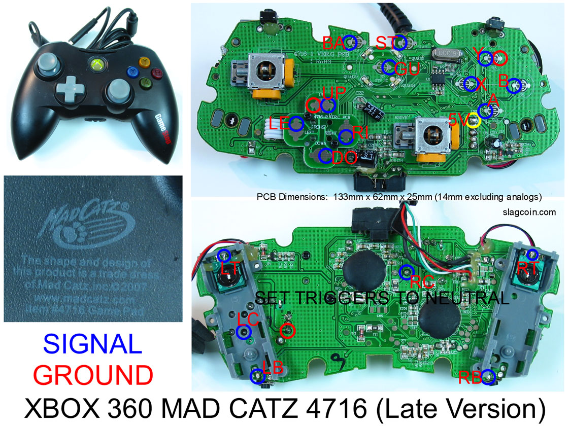
In the picture it says “SET TRIGGERS TO NEUTRAL”
I’m not sure what this means, but I hope I didn’t screw up.
EDIT: Nevermind, I did the ground wrong, fixed now.
Last problem. When I press roundhouse (RT) I get a Down + Left input along with RT.
So when I press RT I get RT + Down + Left together. What did I do wrong?
RT is also where my ground daisy chain ends. Should it go somewhere at the end?
The solder is conductive, and will carry the signal… if your solder points are touching, they will short.
I noticed that there are a couple spots where they are extremly close, or even touching… you might want to re-do those.
Other than that your soldering looks infinitely better than mine.
I think my problems can be half-solved by your alligator clip method, I’m gonna go buy some after work.
Pick up a multimeter and use the continuity function to test whether you have any shorts (e.g. between dpad ground and up/down/left/right), and if the end of the wire is properly connected to the contact points. It’s wise to test as you solder each point or two so you’ll remember what you might have done wrong if things are not connected properly. It’s also safer to test before you plug in, and it makes troubleshooting a lot easier if you run into problems.
The alligator clip method works pretty well, just try to position the clips so they don’t crush the wire too much. Bigger clips usually have taller ridges between the teeth.
You could use a little bit less solder; it makes it easier to avoid accidentally bridging two solder points together. Try to heat up the wire and the contact point simultaneously, then apply the solder more to the wire itself than to the tip of the iron. (Easier said than done; it takes some practice.) The way some of the solder globs are bunched up, it looks like the wire may have been heated up more than the contact point. This could be because the contact points were dirty though, so the solder didn’t want to stick. I usually scrape them a little with a knife or some fine sandpaper (just a little, careful not to go all the way through), then wipe off with some 91% rubbing alcohol on a q-tip or something.
It can be hard to get this perfect when you solder to the surface instead of going through holes. I find it helps to bend the wire a little so it is angled down toward the contact point rather than flat on top, as it keeps better contact to the surface when you remove the iron, which helps avoid the need to glob on more solder to bridge any gaps.