Out of curiosity, is there a “Slagcoin-esque” labeled PCB diagram for the 4736 controller? As near as I can tell, it’s the Gamestop rebranded MadCatz Microcon (sans invert switch).
Thanks!
Out of curiosity, is there a “Slagcoin-esque” labeled PCB diagram for the 4736 controller? As near as I can tell, it’s the Gamestop rebranded MadCatz Microcon (sans invert switch).
Thanks!
Yeeeeah. I’m not confident enough to start slicing away at the circuit board. Seems pretty easy but I might as well just solder directly to the LEDs. Guess I’ll just do like you suggested and create a silly xbox light show or maybe have them all stay on, though the signal would be coming from only 1 connection off the Retro PCB, could that possibly be a problem? Something that usually only lights up 1 LED now lighting up 4?
Tested it in VF5 on the 360 and both triggers work exactly like any other button, even when pressed together simultaneously.
So yeah, the theory of it only being a problem on the PC is correct. Though keep in mind you can just use a PS2 converter and you won’t run into this problem at all while gaming on the PC.
Hope that helps.
Hi, the led guide ribbon broke on my HRAPEX, so I just solder and put hot glue and thought it would be a good idea to check some things with the continuity function of the multimeter.
(I’m pretty sure the guide pcb is the same on HRAPEX and EX2…why wouldn’t ? (mine says “HORI, ver 1.0 1323-13LED PCB”)
so to have
led1 on> connect 1&3
led2 on> connect 1&5
led3 on> connect 1&2
led4 on> connect 1&4
6 is guide +
7 is guide gnd…
then, I played around with the multimeter on the 360 pcb… and guess what I found out ?
Toodles was right  (what a surprise, i know lol)
http://img218.imageshack.us/img218/3193/horiledhackformadcatzarru0.jpg

Edit: not to confuse anybody, when I wrote guide ground I meant the 7th pin of the led hori pcb… not the 360 madcatz arcade guide ground, use any ground you want obviously.
the tension between + and minus on the mardcatz arcade retro leds is 2.00V but the HRAP’s leds will work ok with vcc too.
need advices…
Hi all, I bought a hori fs3 last week and am planning to modify the fs to support xbox 360. I’ll wire 360’s +5v and ground to fs3 to reuse hori pcb’s usb cable for ps3 and 360.
I’m using an ealier version of 360, so I have quite a bit of wiring. Can someone give me some advise on my wiring? I’ve included a diagram of how I’m going to wire the controllers. Thanks in advance.
red/pink = signal
black/grey = common
green = +5v
blue = ground
Thank you very much, kind sir 
That’s exactly what I needed to know.
(Und Spass werd ich damit auf jeden Fall haben :D)
Greetings, complete noob here, with a simple question/favor to ask.
My friend and I trying to convert our X-Arcade for 360. We bought a wireless 360 controller, got schemas to connect what to where but we kind of lack confidence. My friend’s gonna solder the thing and he’s done soldering before but he’s hesitant about soldering the points on the pcb. What I’d like to ask for favor is, if you ever soldered a Xbox 360 pad, can you please take a close photo of solder points? Or if you know any on the web can you point it out? I’ve searched through this forum (found this and this) and couldn’t find any close up photos.
I’d appreciate any help greatly.
V-King>Bitte sehr 
Hey guys I think I found something worth mentionning today:
gamecube trigger don’t work the same on gc mode and on wii mode.
why you ask ?

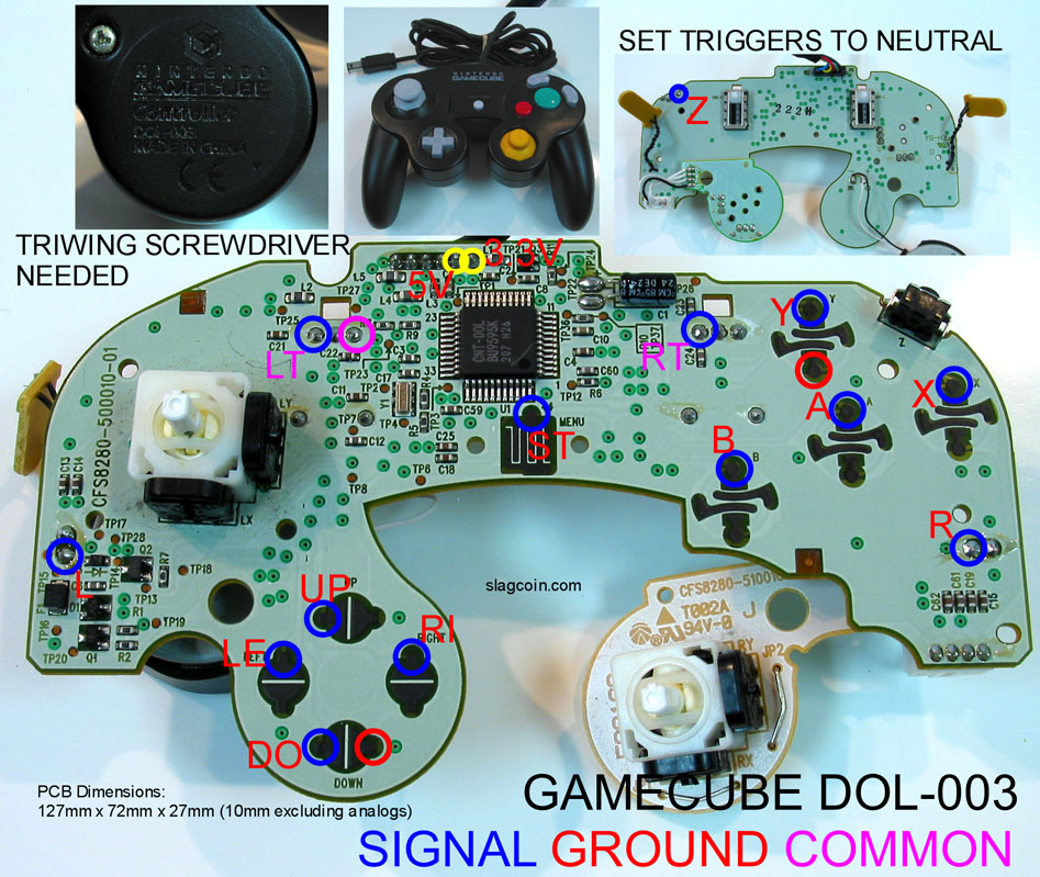
I soldered just the L&R digital points that you can see on the bottom left and right in the front of the pcb.
did it work ? with a gamecube game, yes perfectly…with a wii game (Tatsunoko vs Capcom) NO. an analog trigger hack is needed.
BUT there’s a catch, when the analog trigger is all the way up, I mesure 0V between trigger signal and ground; and when all the way down, +3.3V.
so something hase to be inverted on top of that. 
The triggers do have both an analog component and a digital ‘click’ component, both of which are sent as data to the console. Which one or ones the game pays attention to to treat as ‘trigger pressed’ is entirely up to the game, both on GC and Wii. That’s a game specific thing, not a console specific thing. And FYI, the classic controller is the exact same way.
oh okay, my bad, good to know ! (on GC I tried RE4 and Viewtiful Joe ans both where working with digital or analog, tatsunoko only with analog)
do you have any idea on how to get both “actioned” by a digital button press ?
Yup. Check a couple of pages back, someone hacked the triggers on a classic controller using the two resistors + 1 transistor per trigger to invert the analog signal, and a diode (because the analog setup was screwing up the digital press). If you’re sure the analogs are inverted like you say, then doing the exact same thing should take of it and make a single button press activate both the digital click and the make the analog triggers go all of the way pressed.
cool thanks I’ll try that sometimes  (I’ve got 5 working buttons so far which is enough for tatsunoko I guess)
I have a MadCatz 4716 (Late Version) pad. I am working with the trigger buttons and have read methods to get them to work by either removing the pots and using resistors or by fixing the pots to a certain position. I have a few questions:
If I keep the the pot on the PCB, then what am I setting the pots to? If I’m trying to set the resistance on the pots by hooking up the pad in Windows, then do I want to set each pot so that the triggers are always ON or always OFF? In the event that I were to remove the pots from the PCB and add resistors, are the resistors setting the buttons to always ON or always OFF?
If the pots are left on the board, then what should the wiring look like? Here is my awesome schematic. Can someone please confirm if this is right?
http://img8.imageshack.us/img8/9711/triggerpotrk2kh3.gif
<Naoe Shigen>
Still not going to work. You may not be directly linking the 360 pad commons together, but when you connect each of them to the ground on the hfs3 pad, they’re all getting connected there. You really need to give up on using that early version 360 pad. Ditch it, and get yourself a newer CG pad. There’s simply no easy way to do what you want to do with the pad you have.
-=The Jesster: Gatchaba Goose=-
shit, they don’t work with my converter. This is the first time this happens
wasted money
Has anyone found a box that the mad catz live retro stick will fit into once pad hacked? I have seen others put their PCB in a box to hide all the dirty work. I was wondering if anyone found something easy to get ahold of for the live retro stick?
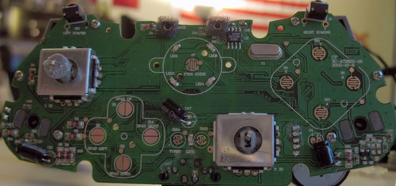
Anyone have a diagram for a Mad Catz #4726? I believe it was called the Mad Catz Game Pad Pro and hasn’t been available for a few years.
Here’s a crappy pic of the PCB, just looking to see if anyone knows if/where the common ground would be.

One last thing I promise…

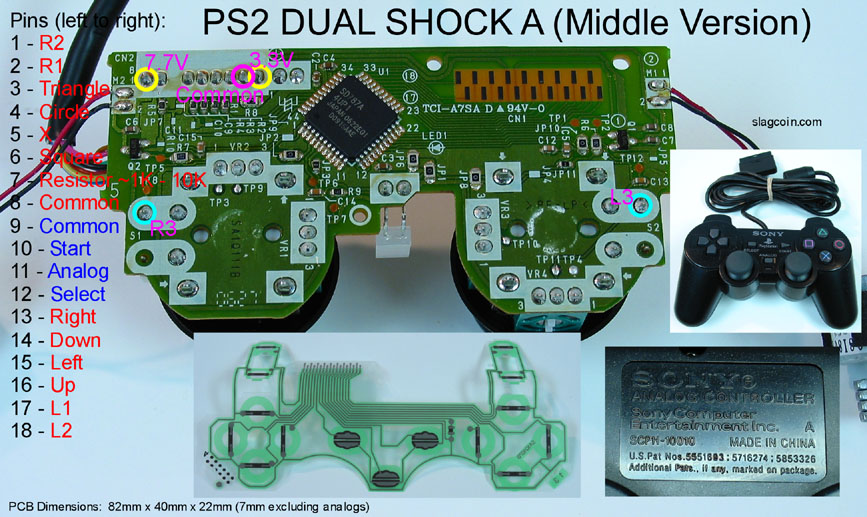
I have this PS2 PCB, and on slagcoin’s site it says I need to put a resistor on pin 7… Do I put both legs attached to the 7th pin or one leg on it and another somewhere else?
Also, anyone know why it says “avoid” on it?
Each sides a button connected to the big mass of green trace, like a ‘sea’ of traces connected together is your common ground. So for example on the Y button, the ground is on the right side of the button because it leads to sea of traces. On the left side of the Y button the trace travels down a unique path not connected to any others. Make sense? Another example; on the B button, the ground is on the… right side. BINGO!
The nicest point for attaching your common ground would appear to be one of those big shiny pads on the d-pad. Also notice how on the signal side of each button at a point along the trace they have made a nice little shiny point for testing the connections. These might be a good place to solder your signal lines.
!!! WARNING: Turns out I may be totally wrong about this. See Toodles’ post further down. I have no idea what he’s talking about with the diodes !!!
Any pics of the Madcatz fighter pad boards for the 360? They don’t seem to have analog triggers (guess) so they might be super easy mods once they come down in price some.
I’d suggest taking a multimeter to that one. There are WAY too many diodes on that thing to assume it’s common ground from looking at it. Check to see how many of those common traces are connected to one of the black wires from the USB cable.