On the cables, make sure you don’t have the wiring backwards on the RJ45 connectors
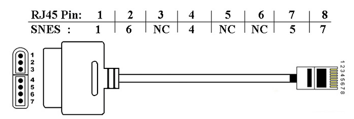
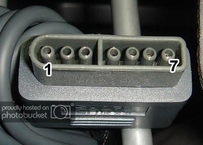
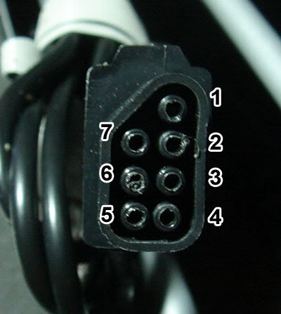
Am I looking at this wrong, or are these two diagrams in conflict?
The second diagram has pin 1 where the top one has 2, 2 where 4 is, 5 where 1 in, 4 where 3 is, and 5 where 1 is.
Can anyone confirm what the correct layout is? In particular, which one, if any, corresponds to this table in terms of which one is GND, which one is VCC+5v, etc.:
Thanks.
Your understanding of the DC pinout is fine.
Just watch out for your Ethernet cables.
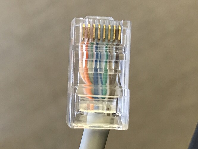
Some standards have wires 1-8 being
- Green stripe/Green/Orange stripe/Blue/Blue stripe/Orange/Brown/Brown stripe
while others have wires 1-8 being - Orange stripe/Orange/Green stripe/Blue/Blue stripe/Green/Brown/Brown stripe
(with the Orange and Green switched around)
Whichever standard it is doesn’t make any difference for console cable purposes, but you’ll still need the right continuity, of course.
I believe he’s asking about the two pinouts being different from each other. How is he to know which is which?
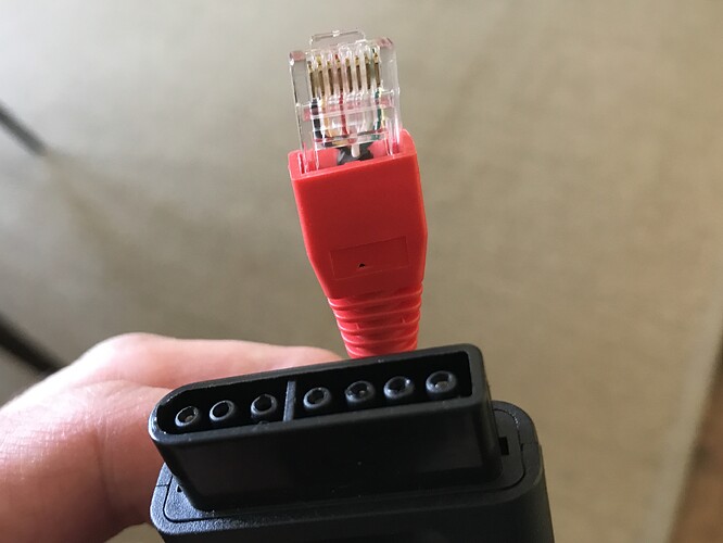
I have a DC cable around somewhere. I’ll verify try to verify which is which when I get a chance. Actually, it doesn’t matter, because if you look at how the numbers correlate to the pins on the Cat 5 they’re the same. For example, Pin 1 (top) or Pin 2 (diagram) both correspond to pin 8 on the Cat 5. If you use just the diagram by itself, you’ll be fine, or if you use the text + photo you’ll be fine. They don’t contradict each other only the naming of the pins on the DC cable.
@PAS.Timothy
My bad, I didn’t catch that part.
@7ony
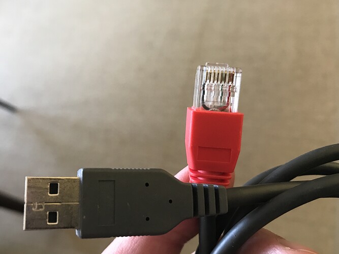
You should follow the numbering that’s part of the documentation for the wiring if you’re following the RJ-45 pinout. The photograph you posted is an old one from another thread.
Bottom line is that it doesn’t matter what each contact point is labelled; what’s important is that the right connection is made: ie, in the case of the Dreamcast cables, the right-connector on the bottom with 2 connectors on the rounded side connects to pin-8 on the RJ-45; or the middle connector on the top with the 3 connectors on the flat side connecst to pin-1 on the RJ-45, etc.
Use a multimeter if you’re not sure what goes where.
You guys were right. I stuck to just using the diagram and it worked. I was able to create a functioning Dreamcast cord and a USB cord.
The next issue I’m having is with Soul Calibur 2 on the original Xbox. Has anyone got this to work? I’ve tested the MCC on several original Xbox games, including Dead or Alive 2, and it works flawlessly. Then, I load up Soul Calibur 2, and it doesn’t recognize the MCC at all.
Do any of the buttons work, or nothing at all? I’m assuming you’ve tried a standard Xbox controller?
I don’t have my original Xbox handy to test for you, and I’m not even sure I have a copy of SC2 for it.  (I know I have SC2 on GameCube and PS2, though).
None of the buttons work at all whether it’s plugged into first or second player. Standard controllers work just fine.
I ordered two MCCs and just setup the second one last night. When I tested it on the original Xbox, I got the same result, everything worked except Soul Calibur 2. Apparently there is some kind of issue with my copy of SC2 (although it works perfectly otherwise) or the MCC simply doesn’t support that game for some reason. Hopefully it’s not the latter since SC2 is one of the main reasons I decided to build a stick in the first place. I’m tempted to order another copy off eBay just to see if I can get it to work that way.
Hi Guys
I totally stumped here.
Have got an MC Cthulu to play MAME (on GroovyArcade PC) and my retro consoles; NES, SNES, PS1, GameCube etc.
I followed the excellent post by Filthy Pants blog
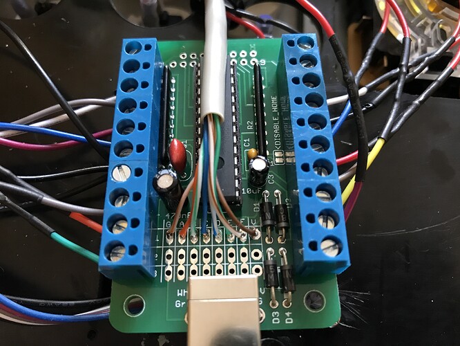
I have soldered an RJ45B to points G-V on the MC and made three cables.
- USB
- NES
- SNES
I have checked, checked and triple checked my continuity right from the MC board, through the Neutrik passthrough RJ45 jack all the way to the pin outs on the controller port and everything matches exactly the diagrams in the post.
I have also checked my joystick & buttons are all getting continuity to the screw terminals on the MC board.
Connecting the MC to a W10 PC via either the on board USB or my RJ45->USB cable works.
W10 recognises the MC as a Multi Console Edition in game controllers app, and I also sucessfully updated the 2.3 firmware like @7ony.
Connecting to my MAME GroovyArcade PC works perfectly well.
Connecting to either the NES or SNES I get nothing. Nada. Zilch.
I have tested on Everdrives and Original carts but get the same. Nothing at all!
And tried power cycling, plugging in and out many many times…
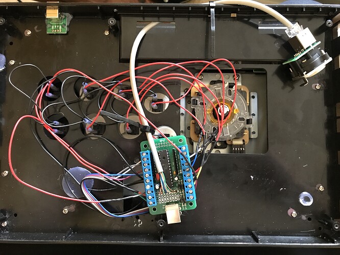
Lastly, my arcade stick is an empty shell of the MadCatz SFIV TE (original wiring removed entirely)
and I connected the buttons to the MC as follows;
top row white buttons 1,2,3 to 1P, 2P, 3P
lower row white buttons 1,2,3 to 1K, 2K, 3K
top row button 4 to 4P
lower row button 4 to 4K
Select + Start to Select + Start
I have not connected a home button
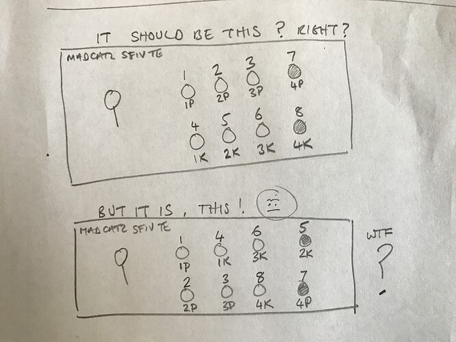
However, in the W10 game controller app, it was all messed up
Ill attach some pics as it will be easier to explain!
Is my MC stuck in a weird mode?
Hope you guys can help, thanks in advance!
That pinout/layout is correct.
When tested on a PC, the PC doesn’t know/care about P1/P2/P3/P4/K1/K2/K3/K4. The button layout does come out a bit unexpected; what you’re seeing is correct. This would be the full mapping of a PS3/PC controller in the Windows Device Manager:

Cheers for that.
So if the MC is working as expected for USB/PC, any ideas why I’m getting nothing on SNES/NES?

I can’t say for sure.
If it’s working on the USB, it does confirm that a) your MCC is working, b) your RJ45-USB cable is working, and c) 4/8 of the RJ45 wires from the MCC to the Neutrik are working (the other 4 are unused for USB, so therefore aren’t confirmed)
My first guess is that something is not at the right wires on the SNES/NES cables, but you said you checked continuity from the end of the plug to the MCC.
I would double-check the wiring/mapping at the SNES/NES cables.
Thanks. It’s triple checked. then checked again. Wires are exactly as prescribed in the tutorial. And continuity from board to port. Are there any button presses I can use to force console mode? I ordered the last MC in stock from paradise, I’m in the UK.
Having spent months trying to make a multi retro console pad hack work (internally to the fightstick) and running into pad conflicts which I couldn’t troubleshoot, I bought this because it was supposed to be easy! Haha! 


Aloha, @roostaar if the board is working on a PC via RJ45 then the only culprit left is the cables you made for SNES and NES. Are you pinning them out via COLOR of the wires or are you actually testing each pin via continuity to know which pin is which? If you are going by color then that’s your problem because there isn’t a standard for colors. You need to make the cables by finding the pin via multimeter and then make sure they’re in the RJ45 connector correctly, since if you have it off by 1 slot it will not work. It’s easy to have it off by a slot. Depending on the gauge and thickness of the insulation can also make it more difficult to properly slot the wires.
Hey @PAS.Timothy and @FreedomGundam
I wish I could easily picture me using the multimeter to prove continuity but its just too difficult.
I have positive continuity from the MC board right the way to the pinot on the controller ports.
I have followed these diagrams to the letter.
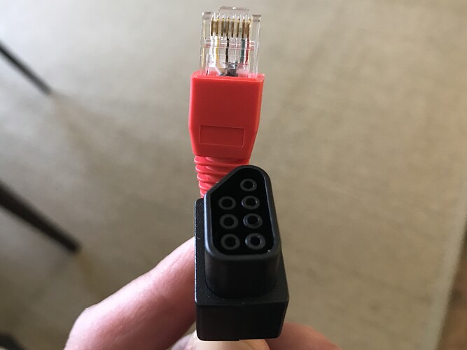
My SNES Cable
Instructions followed
SNES pin - Purpose - RJ45 pin - Cthulhu - ETH Color
1 - GND - 1 - G - Orange Stripe
2 - UNUSED - — - — - —
3 - UNUSED - — - — - —
4 - DATA - 4 - C - Blue Solid
5 - LATCH - 7 - F - Brown Stripe
6 - CLK - 2 - A - Orange Solid
7 - +5v - 8 - V - Brown Solid
On My Cable
Pin 1 connects to G
Pin 4 connects to C
Pin 5 connects to F
Pin 6 connects to A
Pin 7 connects to V
My NES Cable
Instructions followed
NES pin - Purpose - RJ45 pin - Cthulhu - ETH Color
1 - GND - 1 - G - Orange Stripe
2 - CLK - 2 - A - Orange Solid
3 - LATCH - 7 - F - Brown Stripe
4 - DATA - 4 - C - Blue Solid
5 - UNUSED - — - — - —
6 - UNUSED - — - — - —
7 - VCC - 8 - V - Brown Solid
On my cable
Pin 1 connects to G
Pin 2 connects to A
Pin 3 connects to F
Pin 4 connects to C
Pin 7 connects to V
I have just tested these both again and can 100% confirm my cables are setup as the instructions details.
Unless there is something I can do to force the MC into console mode, I can only assume the unit is faulty? Seems weird because the onboard USB works as does the RJ45 to USB cable that I made.
There’s a few variables that make it a hard to test combination, especially with your cables/system of choice.
All cables use RJ45 wires 1 and 8 (for Gnd and Vcc respectively).
USB/RJ45 cables uses wires 5 and 6 for data.
SNES/NES cables use wires 2/4/7 for data.
So there’s no overlap at all.
The best platform to test cables/setup with is PS1/PS2, because the controller cable uses 7/8 wires. Pair that up with a PS3/PC cable, and you’ve gotten all your 8 RJ45 wires tested.
Back on sort of topic, I don’t recall there being a “force” method on the MCC; Google isn’t giving me any results, I’ve never had to do it myself in the past on my MCC-based sticks, and I don’t have any saved documentation/notes with me here at work (they’re on my home computer, of course).
Cheers @FreedomGundam
I’m waiting for a PS1/2 extension cable to arrive in the post. I’ll make a cable for that when it arrives.
Thanks for your help so far. 
Hi all
PS1/2 extension arrived today and made the RJ45 cable. I fully didn’t expect it to work, but, it did!
Even better, the TotoTek PS2 -> Megadrive/Genesis adapter also works on the my Megadrive.
Excellent.
So, you must all be thinking I have messed up the SNES/NES cables, but I really don’t think I have.
I even made another SNES cable with a different lead. All the continuity checks out end to end but it just doesn’t work.
The NES - i get absolutely nothing. No buttons or stick inputs at all.
The SNES - the only button that does anything is 2P. This is sending both button 1 and START commands to the SNES. But thats no good is it. Nothing else responds.
The MC is definitely receiving +5 too as I checked the VVC terminal when connected to the SNES.
As SNES/NES cabling are so similar, it seems too coincidental to me that these both do not work, when the USB, RJ45 to USB and PSX all work as expected.
I can only think that either the unit is faulty, or the firmware isn’t right.
SNES/NES support was added in FW1.5. I have flashed 2.3 successfully (according to the bootloader.exe flash program) but maybe this isn’t right?? Is there a way to verify the FW version somehow?
Does anyone have older FW versions I could try? Maybe downgrading isn’t even an option? IDK.
I really don’t want to have to padhack… 


