I’ve came across a problem when I was assembling the MC Cthulhu. when I was assembling the MC unit. I’ve soldered everything correctly (including USB and screw terminals) but the resistor networks. One of the resistor networks was soldered properly matching the 1 label in the board with the writing, but the other resistor network was placed the opposite from the 1 label on the board.
My question of concern is, am I completely screwed with this board (having me to buy another one)? I’ve tried adding some solder to it and desolder it, but some excess solder is locked into the board. I’ve tried heating it up one pin at a time and push the pin, but no luck. I’ve been thinking of solutions, but they come up with nothing
Frankly, I’ve never been able to properly desolder one of those. The only solution that wouldn’t involve replacing the entire thing would be to take a good pair of clippers, and cut the pack between each pin, so each pin could be desoldered and removed. Then, make sure each through hole is empty, usually with a solder sucker type thingy, and install a new one. I can send you a replacement, sure, it seems weird to charge $1 for the resistor and $6 for priority shipping for it. If you place an order for something else, I can certainly throw in an extra resistor.
well i’ve tried poking the pins with the solder iron and they all refuse to budge. once they’re all in, it’s locked for good :lame:… oh well good thing I didn’t make the mistake on the 2nd kit I assembled. I’ll just purchase one again
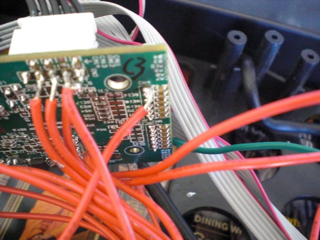
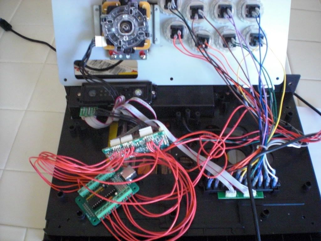
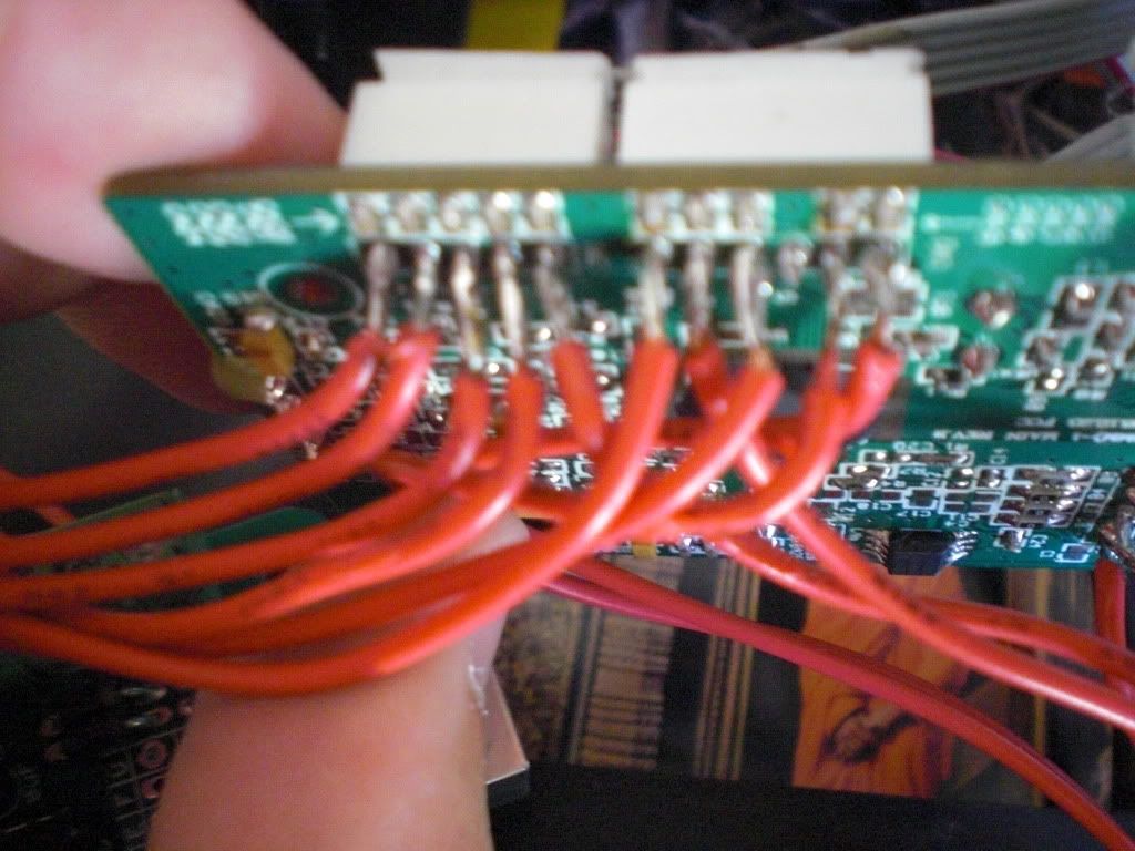
So I was double checking my wiring today and I noticed something interesting. The TE stick’s D+ and D- are connected to the right side of the switch but when switched to the right side in the cthulu board shows up and it works fine on the ps3 and the cthulu D+ and D- are on the left side that when I switch to the left side and plug it into the xbox it doesnt function. Is this normal for the two to work on opposite sides? Also I purchased the MC Cthulu pre soldered so I connected the wires for the D+ and D- from the bottom of the board. Could this be the issue?
I can’t help on the wiring question but for people posting closeup pictures of their soldering jobs, most cameras have something called macro mode, the icon for it looks like a flower
this will allow your camera to focus much more closely than usual and give everyone here a better look at your soldering job.
another tip, if you’re using macro mode your flash is going to be really close to pcb so you should turn the flash off. the flash icon looks like a small lightning bolt, and you want to set it so it looks like a no smoking sign but with that lightning bolt instead of a cigarette. Now you’re picture is going to come out dark and blurry unless you can get some more light in there so use a desk lamp or flashlight or something instead, this will keep your photo from becoming a white mess from the flash.
Any help would be nice. I dont believe the xbox board is fried because the xbox button controller plugs into it and the button still functions for the home button for the ps3. I resoldered the switch and D+ and D- on the cthulu board and the xbox side is still not functioning. Anywhere else I can look to troubleshoot?
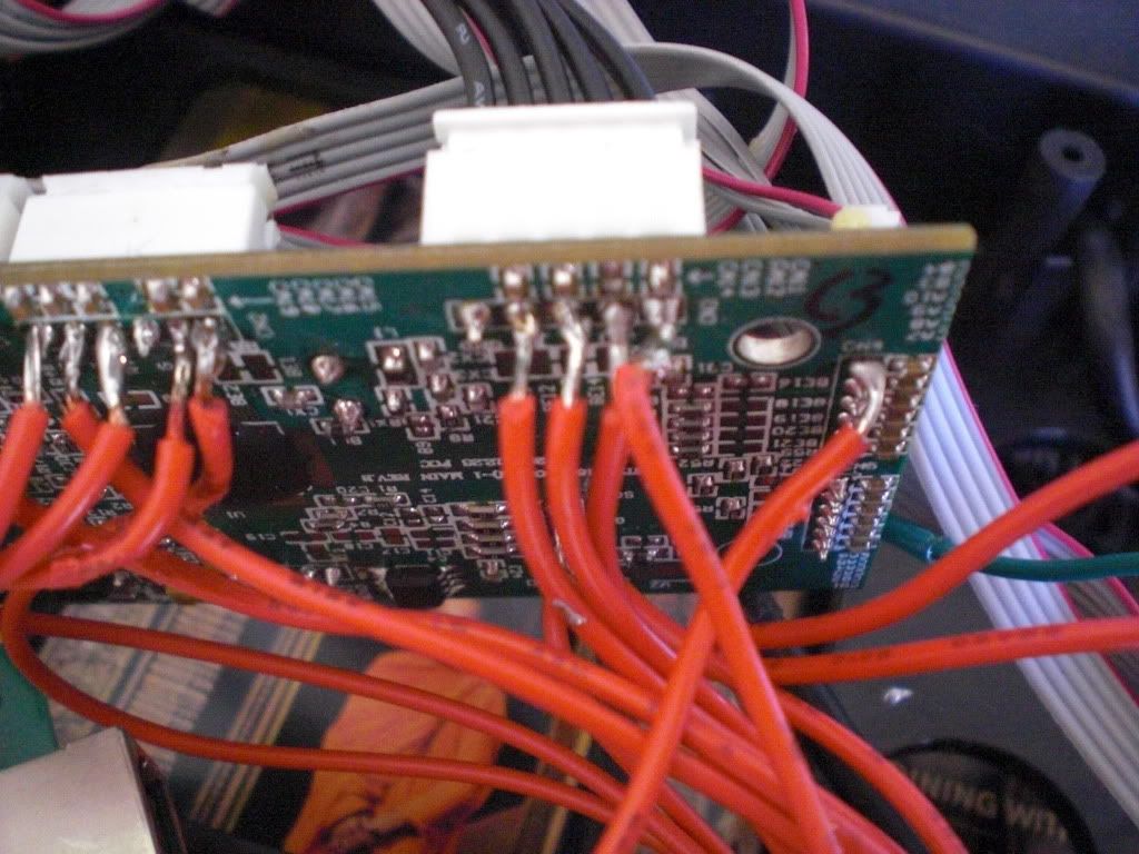
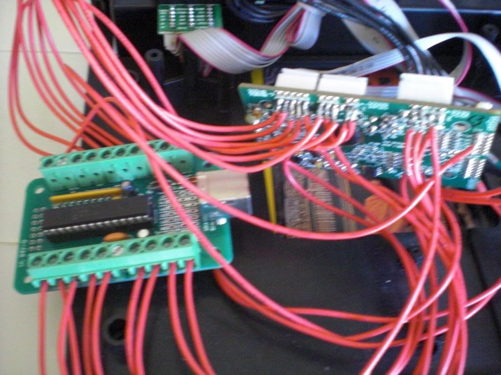
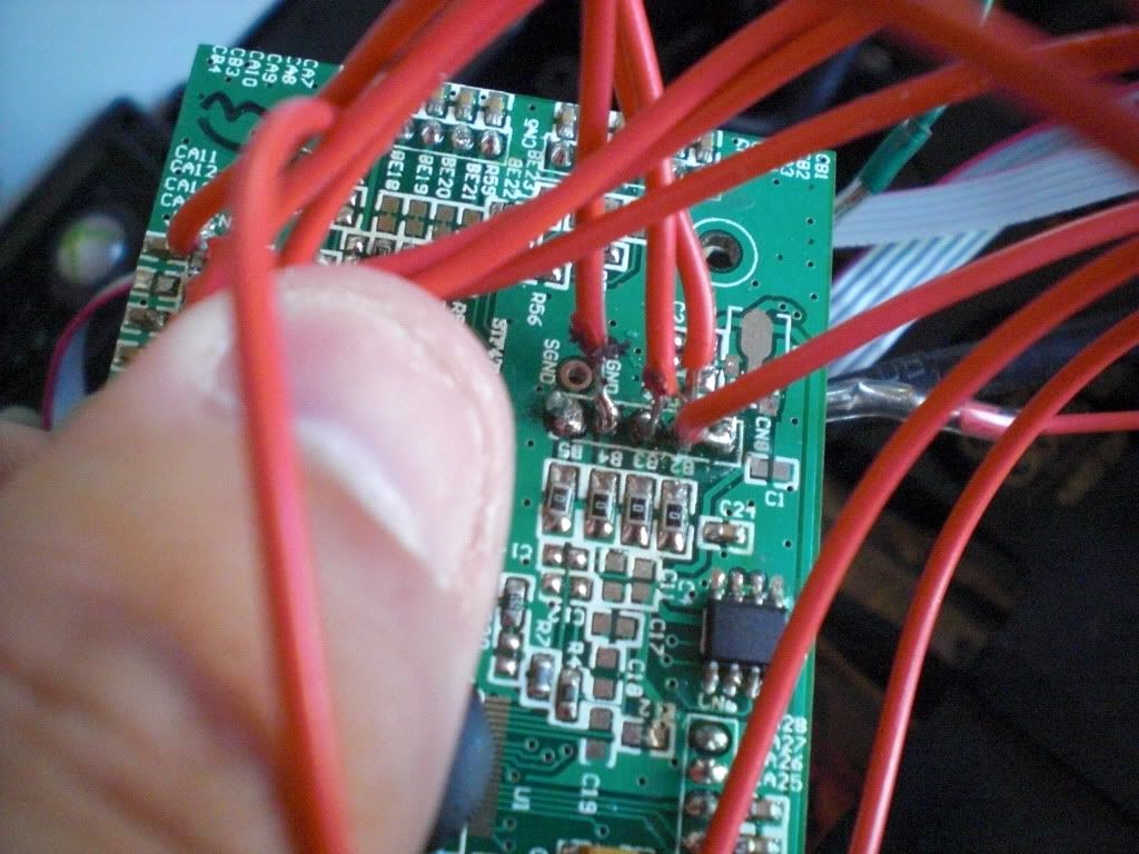
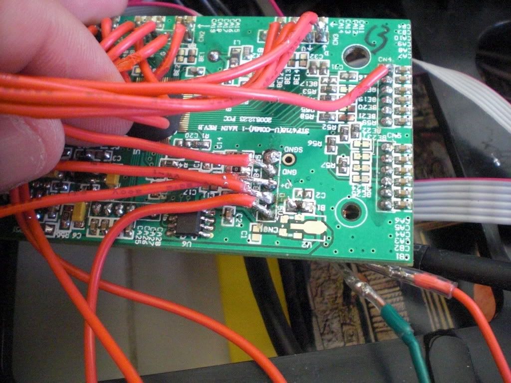
if your 360 side is powering but data is not being recognized it’s most likely your d+/d- on the 360 board. i’d make sure the wires are in the proper order and that you clean off any excess solder that maybe be touching either solder point. also it looks like the +5 on the underside might be touching d- but that may be just the angle of the pic.
it helps to make all your wires a bit more flat to board all parallel to eachother as well so you can visually inspect if something is touching.
ok I found my problem why I couldn’t de-solder to correct my problem… It was that I was using silver bearing solder (which I didn’t notice it’s super hard to de-solder) and with the current soldering iron i have (from radio shack) it would be mega hard to do so even tried a de-solder braid and it failed to expose the hole
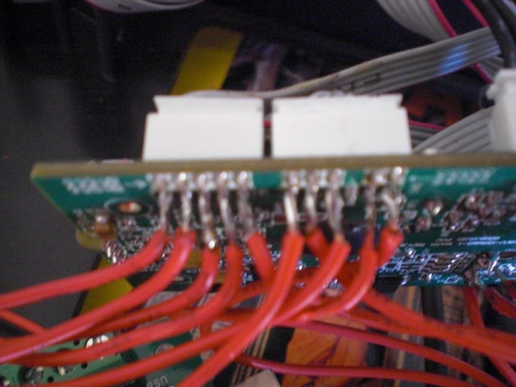
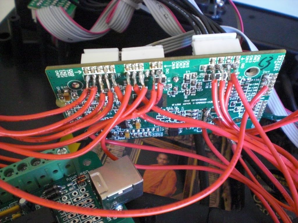
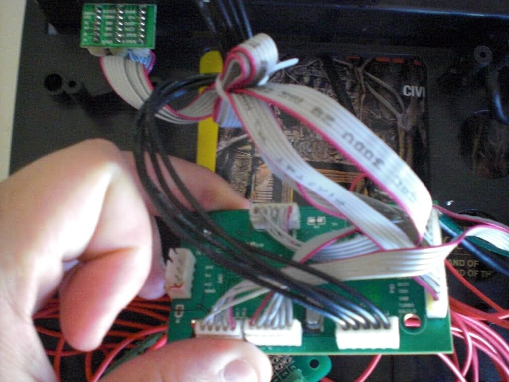
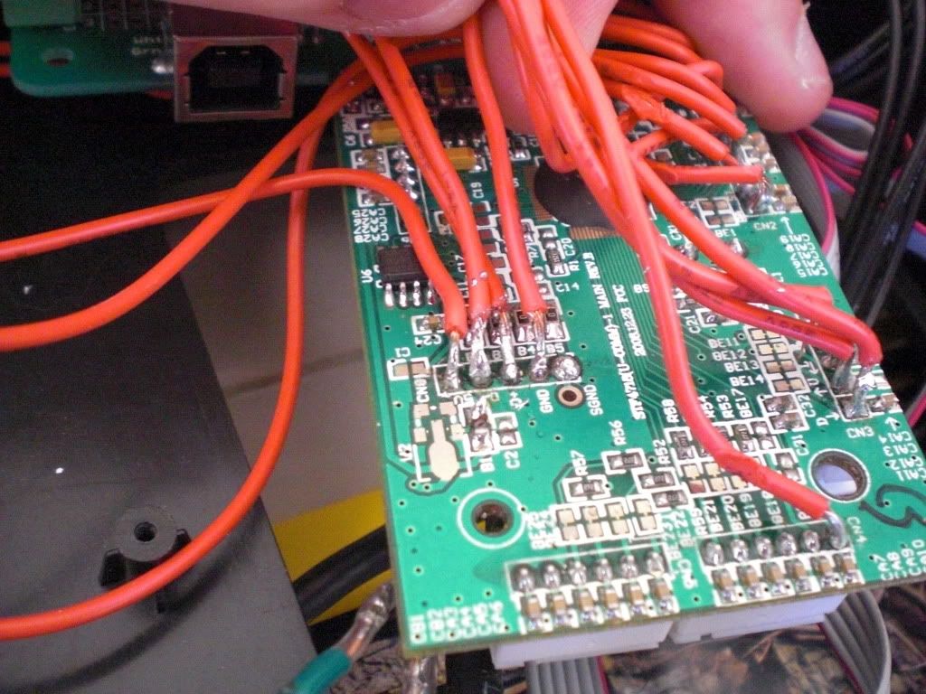
Ok so I have completely replaced the wires that are connected from the D+ and D- from the 360 board. Still no success. I have taken pictures of the switch and board with the new wire.
I also have a video that shows what exactly happens.
have you got a multimeter so you can check for continuity?
It sounds like theres a short somewhere between the 360 pcb and switch…
Looking at the soldering on the DPDT Switch, it looks like an exessive amount of solder, you might want to suck out all that solder, and resolder them and not get as happy with the solder.
Have you considered getting an imp as the switch?
Sorry i can’t be much more help, but i don’t even know how the DPDT Switch works…
For these types of mods, i think 30 awg wire would be much easier to work with
So I just finished soldering the SE pcb and plugging the wires into the screw down terminals of my MC Cthulhu.
Problem is when I plug it into my computer, it doesn’t recognize my 1P button for my SE stick. When I press any other button, then the 1P button appears to be always active, regardless of what I do.
When I plug it in to my computer from the MC Cthulhu cable, the 1P button shows up as always being pushed down, no matter what.
I’ve tested the resistor connection across the corresponding parts from the SE PCB to the MC Cthulhu and they all show low resistance (the ideal) between the points.
All the other buttons except for my 1P button are fine.
EDIT: Decided to read up for an hour or so on google… Found out that I had a short on my 1P button. Frustrating.
Toodles, shot you a PM the other day. Trying to get the naming fixed on my boards.
Due to SF4 not working 2 players w/ keyboard I have to switch from my IPAC to the MC boards and so this is a good time to get the names fixed (get rid of the bad Japanese kanji and random symbols)
Is this something I can do myself with a program? I would love to know how to edit the name myself if possible but if you just need to send me a file or something let me know.
 good thing I didn’t make the mistake on the 2nd kit I assembled. I’ll just purchase one again

 Frustrating.