I just got em today, just finished assembling and trying it out and all I have to say is…WOW! this thing is amazing guys n gals. It works perfect and I tried it out on 360 and dreamcast and it really makes a huge difference. Everything looks like a real sdtv. It doesn’t have that unnatural look that the emulators use if you put your settings right. I have a dreamcast in a blast city and it uses VGA and when playing CvS2 and others the Characters have this crappy crisp pixel look, Put this thing on and you’ll see it look wayyyy better. Bottom line it looks like an sdtv. If that is what your looking for,replicate that old look on a Higher definition monitor or Television, get it. Thanks Toodles!!!
Glad you like it. Please tell your friends. 
Not to derail the thread from its current happy incarnation, but I ordered two v1.1 PCBs and have run across the same issue as detailed earlier (only seems to work on 360s @ 640x480 or 1024x768). Specifically, one of these is being hooked up to a computer for shmup duty.
Bootsector seemed to get one working by feeding external power - any details about what I would need in order to modify on the SLG to get this to work? Any help would be appreciated.
Hmmm, just got my 1.4 PCB today, and it doesn’t appear to be functioning. I can get a picture through it fine, but it never applies the scanline effect. Any ideas on something I could’ve messed up? I checked to make sure I placed the chips and diodes in the correct orientation.
The v1.1 will only work on those; it’s it true that board isn’t getting powered at higher resolutions, but the flip flip is also locked down in place on other resolutions. There’s no safe way to modify that board to work on other resolutions.
Play with all of the slide switches. If that doesnt do it, take some good photos and post them up.
So, best thing to do is reorder and get a 1.4? (Thanks for the quick reply, btw).
I hate to say it because it sounds like a money grab, but yes. In my defense, I posted up the moment I found out about the problems on other resolutions and have tried to be very clear on that point. The 1.4 and coming 1.5 both have tweaks to enable it to handle more than the pre-1.4 versions did. They can tap power from a number of different lines, taking care of the power problem, and also supports negative polarity vsync, which every other resolution but those two use.
If you can assemble them yourself, and dont care about the RGB adjustment shield, you can pick up the v1.4 version immediately.
If you dont want to assemble it yourself, or if you want the RGB adjustment shield, please wait for the v1.5s to be made and released.
Okay, here’s some pics:
http://imageshack.us/g/687/img0039qr.jpg/
I’ve tried all the switch settings, but nothing. The monitor in the pics is rotated, so there should be vertical scanlines in the screenshot pic, but again, nothing. The 360 is running in 640x480.
Cant wait for the 1.5 release to use it on my Dreamcast, Toodles you are doing a great job!
You missed step #3 entirely.
I purchased them as soon as I heard they were on sale, apparently just as the issues were coming up, and part of that joy of being first is being a tester. It happens. Just to confirm, the 1.4 revision will work with things other than DC/360 (specifically, a PC) at any conceivable (sane) resolution? If so, I’ll probably buy more kits and get it working right.
(Although I have a couple of 7404s, so I may attempt to play with inverting vsync and getting external power working on the rev 1.1 first. It’d be ugly, but I’m in the function>form camp anyway.) Thanks for the help.
The v1.4 and v1.5’s were tested with all possible resolutions an Xbox360 VGA cable is capable of (640x480 through 1920x1080), and all possible resolutions the cheapie ebay scaler supports. I personally have not tested it on PCs.
I’ve built a 1.4 similar circuit in a breadboard and it worked fine on a PC on several resolutions (you have to play with the vsync switch in some resolutions). I don’t see an easy way for you to mod a 1.1 board in order to get vsync inverted or proper power feeding the board. Maybe you wanna play with breadboards while your 1.4 kits don’t arrive!
Oh, and you don’t need a 7404 since there’s a spare buffer inside 74hc125 (pins 11, 12 and 13).
I had a hunch you’d figure out what I did before too long. I do like repurposing parts that are already there and not being used.
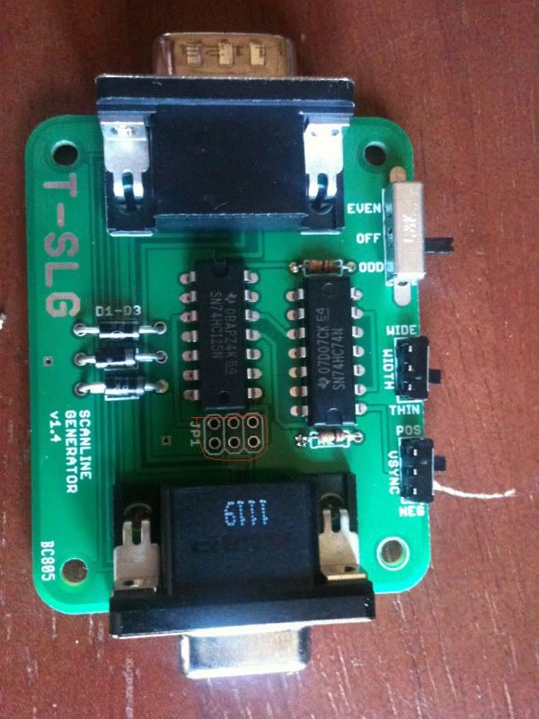
you forgot to solder your points together
Yes, and I really have a big admiration for your creativity in circuits! Using SDA (which “by definition” must be connected to a pull-up resistor) as an alternate power rail was just genius!
And is also why I had to take a REAL close look at my power consumption, and move the resistors to 100k ohms to be safe. The Ebay scaler could source a maximum of 0.95 mA on that line. But just for you, I added pin 9 as another potential power source on the v1.5
YAY! 
But you meant v1.4, right? From the pictures you posted, it looks like the power is coming from a merge of VSYNC, SDA and pin 9?
Nope, I mean 1.5.
Ah, derp. Thanks for the info, I figured it was something obvious, I must’ve been looking at old directions or something, I thought those were for a header or something that wasn’t needed.