This is my first attempt at soldering. And so far I’ve run into a slight issue with the Xbox360 late edition PCB. I have the guide button working, so I’m confident on being able to solder the buttons. However the problem I’ve encountered is the digital direction soldering points . For starters the wavey soldering points, I believe I’ve killed one if not more of these soldering points. As the wire I soldered on broke off with no effort and took the copper contact with it. I’ve looked on the back of the PCB to some of the alternative soldering points. and I’ve also removed some of the silver solder which were on some of those solder points also. I think possibly I left the iron on too long and it oxidized the solder. all I can see is card and no copper.
Is there any way to fix this, or do I have to buy a new pcb. If I do have to get a new PCB would I be better off with the Madcatz arecade stick, it looks a bit better to solder to. Are there any drawbacks to it. Also regarding soldering the xbox360 pcb. I’ve looked at a lot of guides on the internet. But none were specific for Xbox360 pcb to Sanwa JLF. And not very many had decent diagrams.
so far I’ve come to the conclusion that…
Two wires should run from the button soldering points on the PCB to your arcade buttons. I’m guessing this is how it works as I’ve been able to get buttons to work like this.
But for the joystick I’m still a bit bafooled. a Sanwa JLF has four corners. And I’ve been soldering to the silver solder on top of the pCB of the joystick. Is this right? If so then where does the UP and DOWN and LEFt and RIGHt digital wires go? Each corner has ON(NO?) and COM… I’m soldering the Button wires to the ON(no?) connection. So the com wire is for the Common wire from the PCB?Can anyone clear this up as I’m confused . Thanks
Hmm ok I just saw a picture of someone who made a 360 stick with a sanwa jlf. And he used the 5 pin cable to connect to the digital pad. Too bad I didn’t see that before. Ok so I just connect the cable to the joystick and then sodler it to the pcb…
I think that is straightened out. Now I just need to know if there’s a way to solder the 5 pin cable to the pcb if some of the connections have lost their copper.
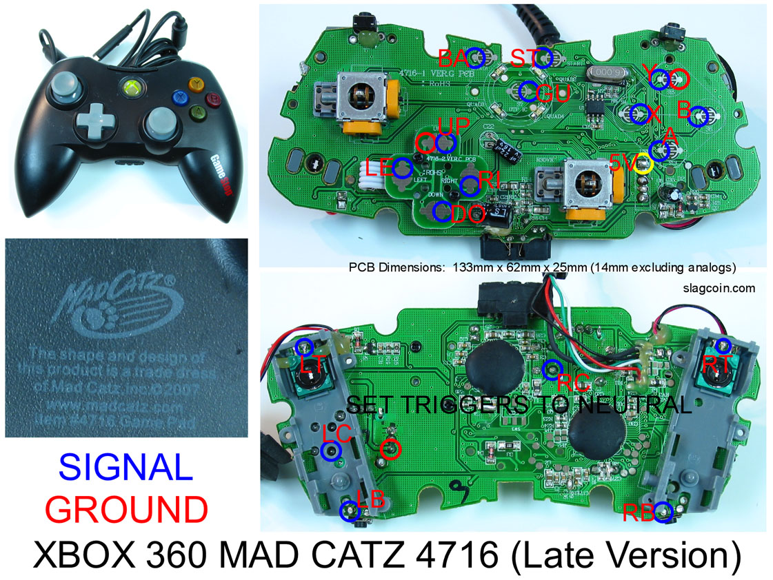
Dude you should have probably asked a few questions before sticking a soldering iron all over your PCBs. Is it the wired 360 controller? Here is a diagram for the new wired version:
If thats the right pad I’ll draw you out the diagram you have to do for each button and joystick.
edit:
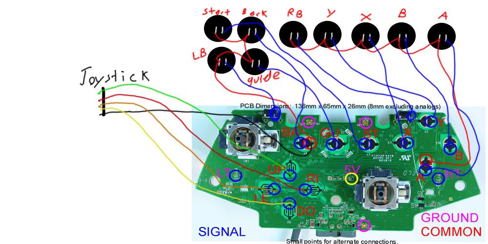
I just drew this up for you. This is exactly what you need to do:
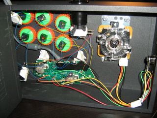
the only thing is that if you use those colours for the JLF you need to make sure your JLF is mounted with the wires coming out the bottom like in this stick:
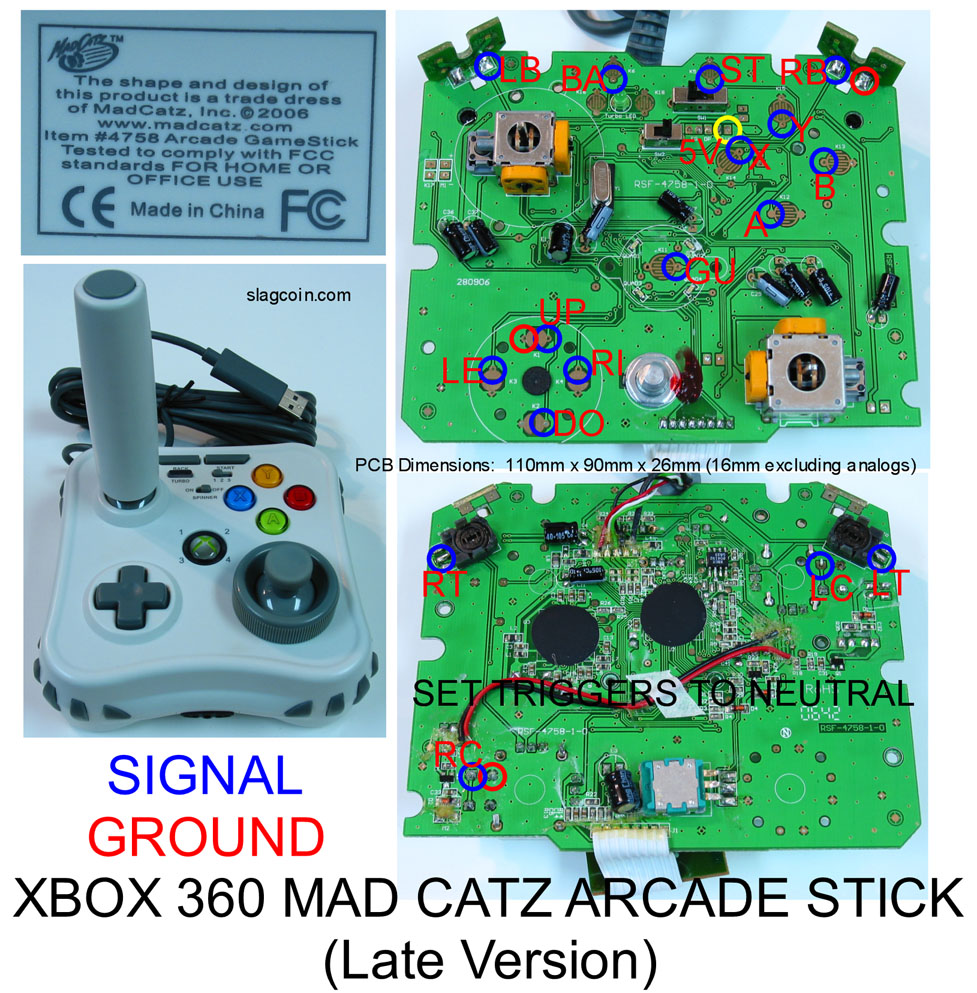
If you did kill the pad and want to get a new one I can give a strong recommendation for the Mad Catz Arcade. I just wired a regular Mad Catz pad and the Arcade was considerably easier.
Alright man. Thanks for those diagrams, they’re much clearer than the other ones I’ve seen thus far. Going to have another shot at this soldering and see what happens.
Well I had a go at soldering onto the front of the PCB. But it wasn’t working. There was nothing happening when soldered onto the wavery lines for the digital direction. And on the back I had burnt off some soldering points earlier on. So I went for the terminal strip instead. It took quite a while and a lot of testing, resoldering and then retesting. had to move the xbox360 and the monitor into the ktichen and keep the pcb plugged in while I soldered.
The joints are very fragile so I put some unibond adhesive on which is for plastic and wood/metal and some other stuff. not sure if that was the best idea but it seems to be working. Going to leave it on overnight then hot glue (or superglue?).
Hopefully this is the last time I have to mess with the digital controls on this pcb. Pain in the fucking ass :crybaby:. big thanks to everyone who helped out though.
^ Those look pretty wild. Hopefully it works out okay for you.
What I’d recommend is that you crack open a couple of controllers that you could care less about. Solder the heck out of every little point you can find until you feel more comfortable with it. That’s what I did and it made me less anxious when working with more expensive controllers.
Good luck. I see how you removed the solder on most of the contacts you soldered on. Hope it works out man. Let us know if the inputs register correctly. I wouldn’t recommend using any type of glue other than hotglue. Other types of glue will be hard to remove. Hotglue once it is cooled will hold but if you need to remove it you can pop it off with a little pressure, I can’t say the same about other adhesives.
You should do this ^ Shimmerman. It doesn’t have to just be controllers, it can be old radios or alarm clocks. Pretty much anything that has a circuit inside. Practice by soldering a wire from one point to another, it takes a little practice but once you know what you’re doing it becomes pretty easy.
Those joints look crazy. Make sure you have a rosin core solder (almost all now right?) and make sure you are applying solder to the wire and pad NOT the iron. Also make sure to touch the iron to the wire and pad simultaneously and apply a little solder to bridge the iron and wire+pad. Watch [media=youtube]I_NU2ruzyc4[/media] and make sure you are doing everything correctly.
I bring up these soldering basics because the joints you posted seem very rough (cold joints possibly) and look like solder carried from the iron onto the wire. Its also possibly that you moved the wire or pcb while the joints were cooling. Doing so will create a weak connection and can come out looking like that.
EDIT: If you have a temperature adjustable soldering iron make sure its at 600-700 degrees Fahrenheit (for lead solder). You should only need to leave the iron on for a second or so and the solder should flow right on. Any cooler, the solder won’t melt properly fast enough. Hotter, you could overheat the components.
Well I finished all the soldering yesterday. The joystick is working normally. I think after soldering onto those terminal strips everything else was fairly straight forward. still going to order a new pcb though and then re-solder it all in a few weeks, but this will do for now.
That diagram is great. Thanks. Im trying to solder a wireless pcb (early version) this weekend. Maybe you can make such a diagram for the early version? That would help me so much. Thanks.
Is that one of the new Gamestop branded ones? If so and if you plan on using the triggers make sure that you check out the thread below. Seems like you have to do a little more with the triggers on the newer gamestop controllers. I’m planning on using the same one so hopefully it goes well for ya.
 . Thanks
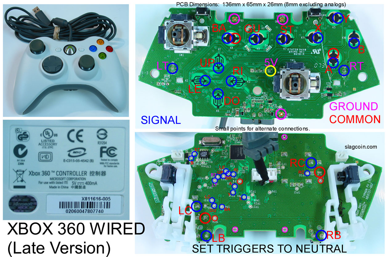
