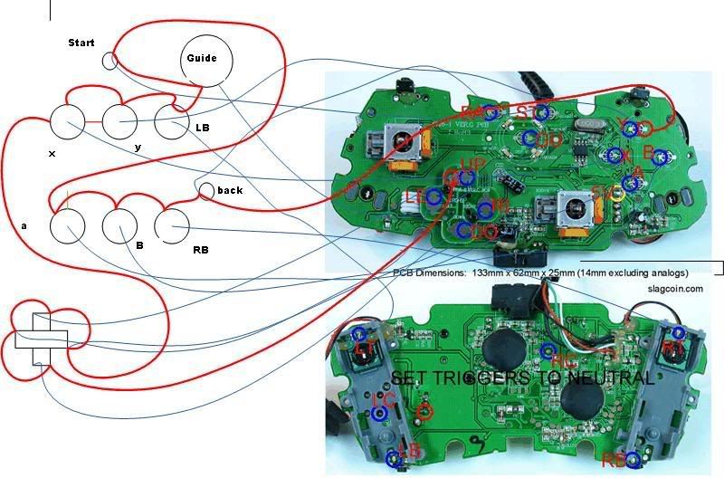
Is there a simular diagram for the first wireless matrix style pcb where the buttons and wires are mapped out? Only reason i want to use this board is i allready had one laying arround and want to make a stick. i have seen the diagram that just circles the commons and the signal wires i am just confused on the buttons that share a common wire. Do i just run one wire from the common side and signal side of each A,B,X,Y button or since the X,Y and B buttons share a common do i run a wire from only one and daisy chain it to the buttons on the controler im making?
Also when wiring up the stick to the d pad contacts do i do the same thing running one wire from the signal side and one forom the common side for each direction?
I was looking on here and was not able to search so if there is one in another thread please excuse me for asking again and shoot me a link. even if someone had a close up picture of their wired matrix board using the contact points that would be helpful so i get an idea of how to wire the buttons and stick.
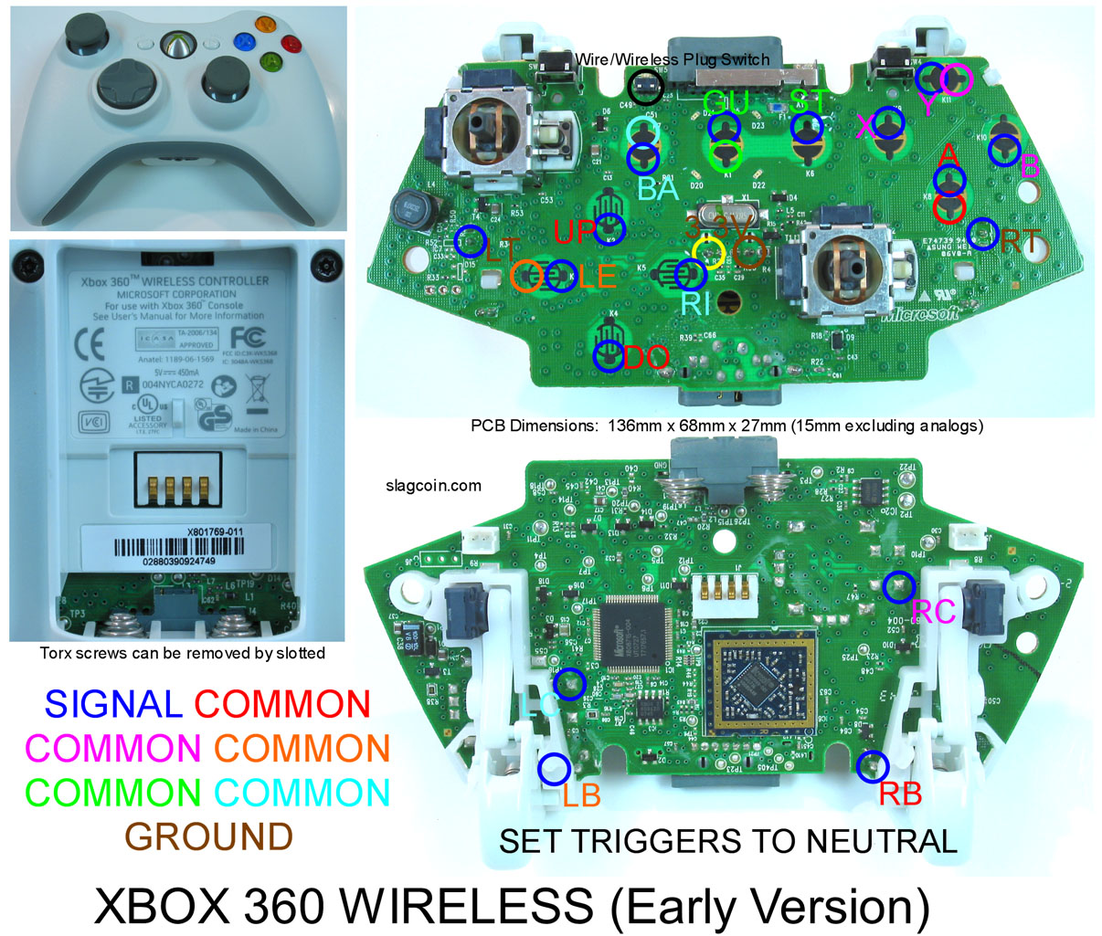
Do you happen to have a diagram for the latest madcatz controller? i’m using a happ competition joystick and happ buttons. here’s how i currently have it wired:
Right now only the left and right on joystick, LB, RB, Guide, and Back work. occasionally the a,b,x, y work. any help would be appreciated.
Thanks in advance
Edit:
I found out that the 2008 version of the Madcatz pad is a little diffrent in wireplacement, i found this on the padhackers thread: