(Authors note – I did a search and found nothing that uses the madcatz fightpad for 360
This is also my first mod that I’ve done and my first tutorial like this so please do give me feedback via pm on areas where I could improve)
So basically this is a tutorial on how to dual mod a Street Fighter 4 TE stick with a XBOX360 Street Fighter 4 Fight Pad. This is great especially if you want to only take one stick to a tournament and not have to worry about if it will be 360 or PS3 consoles.
Total time for the mod: about 5 to 6 hours
DISCLAIMER - THIS IS A MOD AND A HOW TO. I DO NOT TAKE ANY RESPONSIBILITY IF YOU SCREW UP THE MOD OR SCREW UP YOUR FIGHT STICK OR FIGHT PAD.
So here’s basically everything you need to begin.

The necessary stuff
A Street Fighter 4 TE Stick for PS3
A Street Fighter 4 Fightpad for 360
24 Gauge wire
Precision Screwdriver (Philips (+) Head)
Hex Key set (3mm)
Silver Bearing Solder
Soldering Iron
Wire Strippers and Wire cutters
The Optional (but very helpful) gear
Glue gun and glue sticks HIGHLY RECOMMENDED
Multimeter</li><li>Desoldering tool
Electrical Tape
Sponge (helps keep solder from still burning after you cool it off)
Some type of masking tape you can write on
Sharpie or other type of felt tip marker
So after you have all those parts, first thing you’re going to want is your Street Fighter 4 Fight Pad.
There is 7 holes on the back of the pad, 6 that are visible and one that is hidden under the big white sticker. Using your precision screw driver, you’ll want to get all 7 screws out, for the one under the sticker, just puncture it with the screwdriver.
http://i6.photobucket.com/albums/y234/Slashara/TEStick_mod/002_the_back_of_the_fightpad.jpg
http://i6.photobucket.com/albums/y234/Slashara/TEStick_mod/004_stab_into_the_screw.jpg
Once you open that up, there will be another 4 screws to remove from the back to free the fightpad from the front part of the controller
http://i6.photobucket.com/albums/y234/Slashara/TEStick_mod/005_opening_the_fightpad.jpg
The next part is solely optional but it makes for a nicer looking mod.
DO NOT DO THIS PART IF YOU ARE NOT CONFIDENT IN YOUR SOLDERING ABILITIES AS YOU WILL BE WORKING IN A VERY TIGHT SPACE.
http://i6.photobucket.com/albums/y234/Slashara/TEStick_mod/006_a_close_up_of_the_back.jpg
This is the space you’ll be working to get the buttons out
Note: Unless you really want to keep these cheap buttons, you can cut them away so that you are solely dealing with the part that is soldered to the board. Take your time when you’re doing this, the first time I did this mod, I wound up burning out the left trigger button.
Basically with the optional part you’ll be desoldering all the buttons off the PCB.
So after that, you will now have a nice clean (or not clean) board to be working with.
Isn’t it pretty?
Here are the two schematics to how the buttons work.
Up/Down : Right Side
Left/Right: Bottom area
Face Buttons (A,B,X,etc.) It will be on the left side
LB will be the top right hole
LT will be the top left hole.
Back is the top left hole
Start is the bottom right hole.
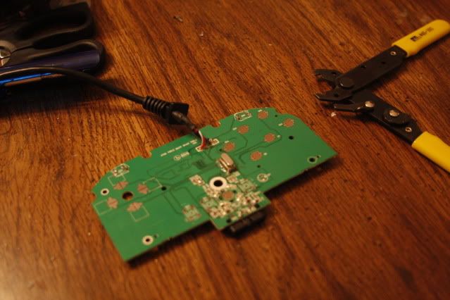
For the guide button, there is a small dot right above the larger button that is a perfect contact point for the soldering.
The pad is completely common ground meaning you need to solder only ONE point and thats it for the ground. I chose the opposite part of the down button because it had a large area and was very simple to solder onto.
Heres the back. You also need to connect to the 5V part. A nice little trick is to expose a bit of the wire and cover the wire part with some solder. Once you do that, place the wire against the 5V connection and lightly press the iron to the wire and it should heat up just enough to connect.
The switch on the back needs to be set to the middle position, otherwise, you’ll be a bit screwed.
So you’ll want to solder each point with a nice length of wire. Wire is cheap, don’t skimp out on it. I used probably close to 15 to 18 inches of wire and cut off a lot of it, but it’s better than filling your TE stick with electrical tape.
So you solder the connection down, then if you have a glue gun, glue that sucker down. If you don’t, you’ll regret it
http://i6.photobucket.com/albums/y234/Slashara/TEStick_mod/012_glue_that_bitch_down.jpg
Okay, so there are all the connections for the wires and everything like that. Now lets move onto the TE stick.
http://i6.photobucket.com/albums/y234/Slashara/TEStick_mod/014_now_for_the_stick.jpg
What you’ll need is the
TE stick
Your precision Screwdriver (Philips (+) head)
a Standard screwdriver (Philips (+) head)
A 3 mm Allen Wrench
So first thing you’ll wanna do is take off the top of the stick by removing the 6 3mm screws and you’ll be treated to a beautiful inside as seen below
http://i6.photobucket.com/albums/y234/Slashara/TEStick_mod/015_the_top_has_been_removed.jpg
Remove the connector for the joystick (and remember which side the glue is on so you don’t reconnect it incorrectly, and unhook all the buttons, write down how they are wired.
Next thing you’ll want to do is turn the stick over and remove the 6 screws keeping the bottom plate on
http://i6.photobucket.com/albums/y234/Slashara/TEStick_mod/016_the_underbelly_of_the_stick.jpg
Then remove the screws on the bottom plate that are covered in red gunk
http://i6.photobucket.com/albums/y234/Slashara/TEStick_mod/017_inside_the_underbelly.jpg
Then lightly pull on the plate, and if you look in the edges you’ll see little white “clip” type things. those are what keep the white sides held on snuggly.
http://i6.photobucket.com/albums/y234/Slashara/TEStick_mod/018_tabs_to_remove_the_underside.jpg
So once thats done, you should just have the basic chassis and be able to work from there
http://i6.photobucket.com/albums/y234/Slashara/TEStick_mod/019_bare_naked_chasis.jpg
Okay, so the first thing you’ll want to do is remove the Home/Turbo block setup with the two small screws on the sides
http://i6.photobucket.com/albums/y234/Slashara/TEStick_mod/020_the_turbo_home_block.jpg
and then after that, unscrew the cable box from its confines, there are two screws, one on each side.
http://i6.photobucket.com/albums/y234/Slashara/TEStick_mod/021_the_screws_thatll_be_removed.jpg
Once thats out, drill a hole on the left side of the cable box about 3/4s of the way up. I drilled it about 5/8s or so, but dremelled it till it was large enough to get the 360 pad dongle through.
After that part is done, slide the dongle and wire through and then rescrew the cable box back into place.
Next part will be modifying the guide button
On the small PS3 PCB, unscrew the PCB from the holder and release it from the side clips
And then since no one uses turbo, there is a small gold circle next to the home button
http://i6.photobucket.com/albums/y234/Slashara/TEStick_mod/021_the_screws_thatll_be_removed.jpg
Solder a wire to there and you can glue it, but that is a bad idea as you won’t be able to actually push the button well. Just make sure its a solid solder connection.
Take the home button and snip the left side off so that it doesn’t hit the soldered wire
http://i6.photobucket.com/albums/y234/Slashara/TEStick_mod/025_make_room_for_the_wire.jpg
Then put the pcb back in the holder, making sure the switches and buttons are all aligned and also feed the wire out thats connected to the home area in the little slot on the pcb
http://i6.photobucket.com/albums/y234/Slashara/TEStick_mod/024b_thread_the_wire_out.jpg
SOLDERING THE BUTTONS
Now to solder the pad buttons.
This is how the small wire cluster block in my TE stick was set up
http://i6.photobucket.com/albums/y234/Slashara/TEStick_mod/wire_block.jpg
So you basically are hooking the button assignments up to the solder points in the block.
These are the button assignments I did. Top is TE stick, bottom is the 360 layout I used based off my HORI DOA Stick
–button assignments from fightpad–
Now when you solder it, the easiest part is to take the wire, feed it through the rubber cap thing, slide the wire into the quick connect clip and solder it down, like so
http://i6.photobucket.com/albums/y234/Slashara/TEStick_mod/027_best_way_to_wire_it.jpg
A loose connection could cause buttons to register only half of the time
and then here is the solder points for the directions and 5V
http://i6.photobucket.com/albums/y234/Slashara/TEStick_mod/028_the_UDLR_and_5v_connection.jpg
U-Up
D-Down
L-Left
R-Right
USB-5V
TIP When doing this, best thing to do is to place some solder on the wire and make it nice and smooth, trim the wire down then put the wire against the solder point you want to connect to then lightly put some heat on the wire, the solder on the wire will heat up making a bond, then you can use a bit more solder on the area
After that, put it all back together, but leave the top unscrewed till you verify all the buttons are working
http://i6.photobucket.com/albums/y234/Slashara/TEStick_mod/015_the_top_has_been_removed.jpg
I Don’t know if you can see it but I put the fightpad in the lower left corner of the TE stick where it fits snuggly. The fightpad PCB also has a little nich in the upper right which you can push against a post in the te stick that’ll keep it nice and tight.
I hope this helps and if you have any questions, let me know via pm!
Again, I searched for “PS3 TE stick with madcatz” and didn’t find anything like this
