I used .110 quick disconnects from focusattack.com with no issues other than them fitting extremely tight. I prefer them to be very tight to ensure a good connection, but they fit tight enough that if you aren’t pushing them on with a good straight force you might accidentally slip and break off the button’s connector. So be careful.
Didn’t notice if you were replacing the stick or not (instructions are in the thread, and it made a great difference for my V3, moreso than buttons), but if you are going the Sanwa JLF route, focusattack.com also sells a wiring harness that plugs right into the PCB that comes with the stick: http://www.focusattack.com/products/Sanwa-JLF%2dH-5%2dPin-Wiring-Harness.html - so QDs might not be needed?
Okay folks, my stick finally arrived after a long wait. I opened it up and installed an Octagonal Sanwa Gate, so far so cool. Now, I have a question: for applying custom stick art, I know I have to remove both buttons and stick. However, since these are board-type buttons…I take that would mean I’d have to desolder them? I’m planning on replacing the stock buttons with Sanwa pushbuttons come December, so unless there’s a way for me to remove the buttons without desoldering them in order to apply the art, I’ll wait till then. Still, I thought it might be a good idea to double check whether it was possible or not.
And I will…but as I have no knowledge of electronics or equipment, I want to have a friend who has a degree on electrical engineering be present when I’m doing the thing as to have someone to supervise what I’m doing, guide me through the process, and overall not ruining the Arcade Stick I worked hard to get. So yeah, I just don’t want to ruin it : P
Wrong thread either way.
This thread is for the Hori Fighting Stick VX/V3. There’s another thread for the Hori RAP VX/V3 SA.
People really need to start seeing the distinction between the two…
I’ve looked through this entire thread and I can’t seem to find it, so I’ll just go ahead and ask…
I got replacing the buttons and the joystick, but how on Earth do you replace the panel so we can put our own artwork on the stick? I have the V3. If I somehow I missed the part in this thread, I apologize. Thanks.
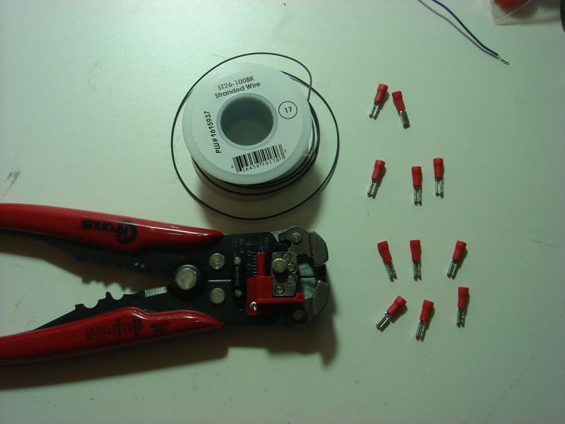
Alright so I got my QDs + wires. Couple more questions to anyone bored enough to help
I desoldered the pcb board off the old buttons, and snapped in the new ones. I think I’m supposed to remove the pcb board completely… I’m guessing I cut the wires off? How should I do this?
I’ve read in this thread that you use something called a “daisy chain”. Is this for the ground wire? I could probably search on youtube how to make one if this is the case.
So I think I’m supposed to connect one QD + wire to one connector on each button, and the other connector goes to the daisy chain. Then you solder each wire cut off from the pcb to its respective button, and the ground one is soldered to the daisy chain. Am I correct in this? or am I completely wrong haha
Thanks again, here’s a picture of what I have so far:
The PCB that the buttons were on can be removed completely. Personally I cut the ribbon of wires going into it right off at the base of the board. Memory is fuzzy, but it seems like that ribbon was too short to directly put QDs on and plug into each button. I made 6 wires with QDs on them, and soldered each wire to the respective wires on the ribbon cable to give me the slack plus let me use the ribbon cable’s nice plug hookup on the end. I believe the wire-to-button info is on one of the PCBs.
Yes, the ground for all the buttons is common so you can run one wire between all of them. You can put 2 wires per QD, so you can literally make a small “chain” wire that jumps from one QD to the next all the way back to the ribbon cable’s ground wire. A good image of one is here: http://www.focusattack.com/10-connection-110-ground-daisy-chain-wire/
Yep. One side of the button goes to the ground daisy chain which goes to your PCB’s ground (via the ribbon cable, if you don’t want to solder and possibly mess up the PCB itself), the other side goes to the button’s appropriate spot on the PCB (via the ribbon cable as well).
Thank you very much. I ordered the crimper/stripper that BartStation suggested (thanks!) and it seems the last thing I’m missing is the female QD + connector thingies. Could anyone suggest a good website to get them and which ones to get? I had to make a few trips to Radioshack and back. http://i730.photobucket.com/albums/ww301/rtdzign/Misc/DaisyChain/DSC03735.jpg What kind of connects are those?
.110 are for the button, if you’re not using a 5 pin those are .187
Ebay is your best bet for bulk. If you’re only looking for a few, try focus attack.
I just tried soldering for the first time, using the method where you touch the jointed wire with the iron and touch the other side of the joint with solder. The thing is, when I touched the joint with the iron, the wires started to smoke immediately, and although the soldering worked, it doesn’t have that shiny silver coat; instead it looks a little bit charred. I must be doing it wrong.
Also, I’m not using any sort of harness so I guess I need .187 connectors? I apologize for the stream of questions, I just want to make sure I do this right. I just know once I’m finished it’ll all be worth it.
Here is an image of the soldered wires. It looks like it’s burnt! I tried it twice and it came out with the same results. Those other wires shown are from the original PCB.
These wires are the ones I bought at focusattack and are attached to the buttons. I cannot tell if they have this “clear” insulation. Maybe my iron is too hot? It is 30W.
The wire itself looks perfectly usable, and now that I think about it my rosin core solder smokes when I am applying it as well (which is the flux doing it’s job, I believe?). When I look at your first pic, from what I can tell it looks like the solder flowed correctly into the wires and bonded (which is what you want), but it looks like the heat may have discolored things, or even got the wire hot enough to burn the insulation down below the stripped portion. I’m not a soldering pro by any means, but in general I do the following:
If your iron is adjustable, find a heat setting that melts your solder and try not to go much above that.
Clean and “tin” the iron tip. Some irons come with a sponge or some other type of cleaning device that gets rid of any contaminants on the tip (tar, plastic, etc). Once this is done take a bit of solder and apply it directly to the tip so it’s a bit wet, this helps transfer heat from the iron into the wires MUCH faster.
Apply the iron to the piece to be soldered, the goal is to heat up the object just to the point that it melts the solder itself, then apply the solder to the object (not the iron). If you do this right you’ll notice the solder kinda flow in between the wires, and stay there when the iron is removed. Use caution to not hold the iron there too long, since the heat does travel and can mess up your insulation or components.
This step is kinda optional. If you mess up and get your tip dirty or excessive with solder, just clean it and tin it again.
If you have some spare wire, i’d try making several little joints just to get the feel for how long you need to keep the iron there and to build up some speed in application. The hardest part of soldering to pick up for me was doing it fast enough that you don’t burn up your stuff in the process. I used to repair broken laptop DC jacks, and I can’t tell you how many I have melted the plastic parts out of by keeping the iron there too long.


