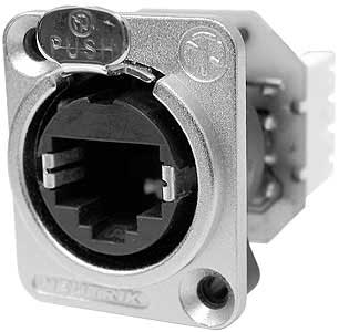
I’ve come to discover that the Neutrik RJ45 adapter that has become oh-so-popular as of late seems to be a rear mount only, and really, only mountable through thin material (sheet metal/thin plastic). Problem is the box I’ll be putting this into is of wood. A little bit thicker than intended by this method. The Neutrik USB equivalent is shaped in such a way that it can be front mounted, but with how the RJ45 variant is designed, it would seem that it really was never meant for this same purpose. Any ideas on how best to tackle mounting this sucker in on a thick/wood box? Or perhaps I’m missing something and there IS an RJ45 adapater that can be front mounted a la the USB one.
Get a 2 inch X 1 3/4 inch thin metal plate or acrylic. Drill 24mm hole in it. Mount Neutrik to that plate and make 2 mounting holes on the sides. Drill a 1 1/2 inch hole in your wood case and screw it on.
Belated Reply
Hmm…
This idea will work, but seems like it’ll look funny against the wood. I think if I can find out a superior method to this, I’d much rather go that route, but I’ll take this idea if I’m unable to find anything better. Perhaps it won’t look so bad if I cut a circular shape instead of rectangular, or perhaps cut a piece big enough for both my USB Neutrik and RJ-45 Neutrik.
Any other possible solutions out there? I’d really rather not have this slab of sheet metal on the front if I can help it.
I’m afraid I’m not fully understanding the problem.
If you mount this inside a 24mm hole, the plate around it would fully cover the opening. You’d see the metal square, but I’m not sure if there is a way around that. Or do you mean the mounting method someone used in one of the cthulu threads, putting the square metal inside the box and drilling a round hole to expose the connection, leaving just the circle around it exposed? If thats the issue, you may have to get a router and shave off a bit off the back side of the case, you could do the same with a chisel as well if its sharp enough. To do it by hand with a chisel, tape off the depth you need to remove on the end of the chisel (meaning wrap masking tape around the tip of it, leaving just enough exposed to get the depth), then mark off the sides of the jack onto the inside wood. Take a mallet and tap into the wood, you’re going to want to lightly carve out a checkerboard grid, keep the squares small, then set the chisel at a 45 degree angle at the start of the grid and give it a few taps, that will cut out the small squares. Sounds more confusing than it actually is, but it works pretty well. Chiseling out the squares like that weakens the inside of the cuts enough that a sharp chisel will have no problem removing it. Just go easy with it, its the inside of the case though, if you mess up here or there no one is going to see it.
The problem is that this jack isn’t designed to be mounted into wood, it’s designed to be mounted onto thin metal/plastic. The circular portion of the jack is 24mm, but the inner part is much wider and will not fit into a 24mm hole.
Here’s what I did…
http://forums.shoryuken.com/showpost.php?p=7341777&postcount=111
Also did a full plexi back for this one…

Ultimately, this seems to be meant to be mounted to something thin, which MDF is very much not. Also, this can’t be disassembled in any way, so neither a direct rear or direct front mount option seems to work all that well.
A front mount is literally impossible on its own due to the PCB mounted on the back is the same size as the plate on the front, which, without being able to disassemble it, coupled with the fact the main plastic housing sticks out and around to supplement the screw holes, means the entire device is the same size as the front plate. Then there’s also the fact there’s this thin sheet of shielding that is literally solder mounted into the PCB behind it. At first I considered cutting it off, but then inspecting the rest of it led me to believe that’d just waste my time.
Rear mounting can work… but that also means it’s sunk behind all that MDF before a connector can get back there, not to mention access to the release tab is virtually impossible with that depth. One way or another, I only see a crude chiselling job being the only way to work this one right, and it’s not even how I’d want it to be, considering the USB Neutrik will be front mounted and not match… thus my OCD kicks in. 
I ended up ordering a different Neutrik RJ-45 that had simple pinouts but seemed to have wasted the $5, as the pins are super weak and too close together to use simple header connectors on, though the shape is considerably more workable in terms of front mounting, as I could simply drill holes slighly larger than the screw locations that only go part way through, drill my 24mm hole in the center, then just slide it in. Sadly, that’s where I’m stuck as the pins just don’t seem to work as I’d have like them to have. Kinda back at square one but still not exactly thrilled with what may be my only option.
I suppose that’s better than the sheet metal, and the way you did it does seem a lot better than what was done in the thread you linked. It looks like something that’d work better for the MAS, seeing as how the edges of the MDF go beyond the back like that, letting a full piece of plexi make it flush. On the customcade, it’s already flush so it would actually stick out. Definitely better though.
Pardon my ignorance but I’ve seen people putting RJ 45 ports on their joysticks and whilst I do understand the need for a usb port I can’t grasp the use of a RJ45, could anyone enlighten me please?
generic 8-pin output for those using the MC Cthulhus. Lets you just use, say, a PS2, GC, etc. extension cable, cutting off one end and putting the RJ45 connector on that end. Saves having a bunch of cables permanently connected, as well as being able to use more than just 3, if necessary.
Try mounting it like this:

It’s more work and requires more tools but will look nice. you can use lexan instead of a metal plate. Get wood screws that won’t go through to the other side. Also the cable hole will be counter sunk, so maybe it might be to deep and need some extra routing.
On another stick I made I used a regular RJ-45 fit into heavily dremeled door strike plate.
^extremely creative solution. Love it.
However, if you still need to use a damn neutrik because their cables are awesome, then why not use a CAT 6? Cat 5 or cat 6 all the same twisted copper for us joystick users eh?
http://www.neutrik.com/fl/en/misc/210_2140927947/NE8FDY-C6_detail.aspx
Fits right for wood too… 
Yea CAT 6 would work… a cat 6 cable has shield in the middle to separate the 4 pairs of twisted copper and rated for longer range for running a cable. (Less interference, longer run - That’s only important for the networkers) For joystick application, it shouldn’t matter. All we care is that its a copper cable that can connect the right wires in the end.
EDIT
It is substantially more expensive… it may be worth it if you are planning building the ultimate joystick of your dreams.
http://www.mouser.com/ProductDetail/Neutrik/NE8FDY-C6/?qs=sGAEpiMZZMvQhAhQbXdbBoTnhlbmMnSONfojAgaIIjQ%3D
Also if you were wondering if the neutrik CAT 6 port will accept CAT 5 cable (cheaper), it will and vice versa.
Hope this helps.
I suppose this is a topic I should have thought about before 
I’ve got a couple of cases from ecksnine coming in, that will have 24mm holes drilled for neutrik jacks, but I dont think those will work for all of the same reasons listed in this thread. I just placed an order for some of the NE8FDY-C6 linked above (thank you by the way). I just can’t make out what the ass end of it looks like and how the wires or cable connects to it, so I guess I’ll have to wait and see. if the NE8FDY-C6 does the trick without too much headache, I’ll post up pictures, but I’m afraid I may have to do a little filing/rasping of the case to let the rectangular corners of the ass end go through the 24mm hole.
From the neutrik website, download “assembly instruction” PDF. It should show you how the CAT 6 cable should fit. Lets say when you punch the CAT 5 or 6 cables down in the neutrik jack according to the 568B standard diagram, you should also stick to that standard when making your cables too…
http://www.lanshack.com/make-cat5E.aspx - same for CAT 6
More of the same, less confusing -

According to Acceptablerisk’s tutorial the Cthulhu should be connected like so:
Pin 1 Pin 2 Pin 3 Pin 4 Pin 5 Pin 6 Pin 7 Pin 8
G A B C D E F V
If we’re using 568B wiring scheme then here’s what each color corresponds to (RJ45 JACK):
pin1 - G - OrangeWhite
pin2 - A - Orange
pin3 - B - GreenWhite
pin4 - C - Blue
pin5 - D - BlueWhite
pin6 - E - Green
pin7 - F - BrownWhite
pin8 - V - Brown
For the Neutrik Jack in the rear end, you notice that it shows you the wiring diagram on the top edge sticker - as mentioned before use 568B standard so that you know your RJ45 will come out expected from pin 1 to 8 like above.

EDIT
Toodles, on the assembly pdf, it seems like you can pull out the back part when you do the wiring - meaning you do not have to file or rasp or very minimally.
I noticed on the NE8FDY-C6 that there’s no plunger release mechanism like the others. Does that mean it doesn’t lock in place? I’d almost prefer that providing it has a solid enough connection, like the USB connector.
Correct, it won’t lock in place if using the ruggedized plugs. In all honesty, you’d have just as much trouble mounting this one as the original one mentioned in the OP.
Really? This looks like it’d just slip right into a 24mm hole from the front…
It will most likely slip right in from the front. When you mount it, you mount it without the rear end that pops out. After you mount it, you can try to snap the rear end back to its place. If it does not fit, you know what to do… file, rasp or better yet as a wood worker, get a forstner bit that’s bigger than 24mm and make a recess from the inner side of the case frame.
CAT 6 for neutrik has its own set of locking cable. http://www.markertek.com/Computer-Related/Computer-Data-Cables/CAT-6-Cables/Neutrik-USA-Inc/NKE6S-1.xhtml Looks cost prohibitive. Good thing is if you buy one cable, you get two ends…
If you don’t have the money, the best altnernative might be a snagless CAT5 cable. Get a 1 footer, cut it in half and use each end to connect to a game console controller of your choice. Snagless cables have slightly less chance of the RJ45 tab breaking. Also if you make your own patch cables, the wires later might come out from the RJ45 plug. This snagless cable is molded so it has no chance of the wires coming out of the RJ45 plug. http://www.cablesandkits.com/cat5e-ethernet-patch-cable-snagless-foot-gray-p-207.html
so, I ordered this guy, and it definitely looks like the ideal connector for me, but one thing is making me paranoid. Now, I know it has to be pure paranoia, as logically it’s inconceivable, but the label affixed to the adapter that numbers the wiring… they don’t swap, do they? 'cause the color swap of the right set of each has me confused, even though the 87456321 order should be the same on both the RJ45 side and the wire side… but then the color guide goes Purple/Blue/Orange/Green on the RJ45 side and Purple/Blue/Green/Orange on the wire side… like I said, I’m probably just paranoid, but I need a second opinion before I go doing something somewhat permanent (looks like an absolute pain in the ass to disassemble without breaking it).
You are not seeing things. Its not the same order on RJ45 and the wire side. Basically if you punch down the wire side as the diagram shows 568B, it should match the RJ45 side.
:wtf:
so, as I understand it, if I want the RJ45 jack to be what it normally would be when I go to connect a PS2/GC/etc. cord to it, the GABCDEFV pins should, instead of being:
87456321
VFCDEBAG
should be:
87456321
VFCDAGEB
'cause if the color coordination is how I understand it, the pinout from RJ45 to wire goes from 87456321 to 87452163. Unless I’m totally misunderstanding it all.