If you ordered .110 quick disconnects then you should probably get 22 guage wire, as that is the smallest wire that those disconnects can use.
Thanks.
Fuck. Guys, I was trying to repair a button, and when I resoldered everything, the buttons wouldn’t work. Joystick still does, though. Any ideas?
This will be my first mod, I ordered the following:
8x Sanwa Buttons
Sanwa Octi-gate
Quick Disconnects
Seimitsu Bubble Balltop
I don’t expect to see it for a while but I will be moving this weekend so I will be busy with getting situated for a while anyhow.
My guess would be when you soldered in the new button you bridges the connection or dripped solder somewhere on the board.
I’m thinking of modding my FS3 with new buttons and PCB. Anyone know the size of the start/select buttons?
I think its back in the thread somewhere, someone said like 12mm or something but I might be making that up 
Ok I’m embarking on my first major Joystick modding adventure. Here what I’ve got so far.
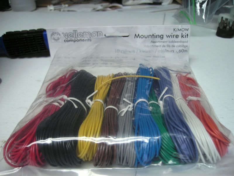
I’ve started with a FS3 one of these http://www.gamestop.com/Catalog/ProductDetails.aspx?sku=802511 (I bought 2 actually). I grabbed some of this wire from electronics123 http://www.electronics123.com/s.nl/it.A/id.1931/.f
I’m a Soldering novice but here’s what I’ve got after a night of soldering.
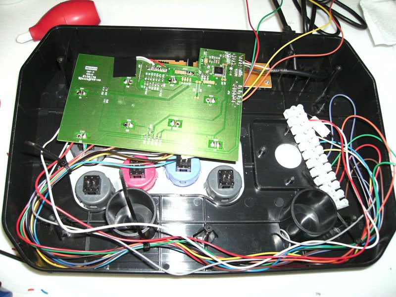
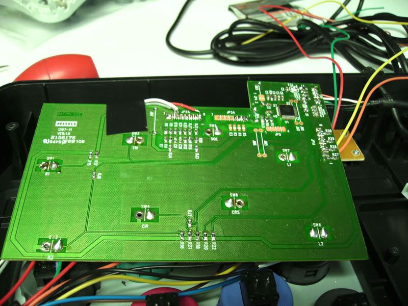
I’ve got another euro strip which I plan on cutting 4 terminals off of and using those for the joystick wires. I’m not sure if I’m going to hook up R3, L3/ RC, LC yet or not Soldering those small points where the smaller PCB connects is hard for me! I’ll solder up the 360 PCB next and match the colors/buttons on the same side of the strips. Then when my parts get here, I’ll wire those into the other side and be good to go. Sometime before that I’ll have to learn how to wire the switch to toggle back and forth between modes.
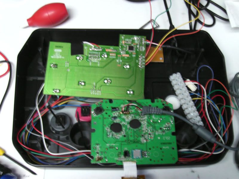
Here’s the tentative placement of the PCBs within the stick. I’ll have to do some dremeling to make it work. The will be shifted more to the left to make room for the Joystick.
What problems do you see me possibly running into?
I would suggest you make sure to put electric tape all over the inside part of the bottom plate. I basically just stuffed my PCB into the box and found that the bottom plate actually conducts electricity and my PCB short circuited a bunch of times. Especially with two PCBs like that, you should find a way to avoid that.
Also, I always thought that it’s possible to make more room in the stick if you cut off those two plastic support rings, but I’ve never tried it myself and wouldn’t know the long term effects of doing that.
I was planning on covering the bottom with duct tape (for cost purposes), that’s non-conductive right?
As I was thinking last night in bed I think I may have a problem with wiring the Start, Select and home buttons to work on the 360. Seems the ground point for those wires is right next to them on the board. So If I just solder wire to the under side of the signal wire there’s no real need for the current to go that way as opposed to takeing the shortest path to the on board Ground.

I think I’m going to have to cut the ground wire and connect it to my own to force the signals to travel through the longer circuit for both boards. I’m just not sure how to set up that wiring.
nobody?
Yes, I did try using the stock Hori shaft in the JLF stick to deal with the issue of the over-long JLF shaft not fitting in the case. If you go back and look at my previous post right here, the image I posted of the underside innards has the Hori shaft installed. You can use the Hori actuator and the other Hori piece that the spring sits upon - I don’t recall the name of that part. It fits! No need to modify anything else. You do, however, need to grind down both the actuator and the other part to better fit in there. If you don’t, the fit is extremely tight, so tight that there is literally no throw at all, and a very small dead zone, unusably so.
However, I will warn you, ultimately it doesn’t work well. The JLF winds up feeling worse in performance than the stock Hori stick. I tried using the stick so outfitted, but was unhappy with it. I compared another Wii Fighting Stick I have modded with a straight JLF with the shaft ground down, and…the stock JLF wins hands down. This doesn’t even feel like a JLF anymore. Maybe some people would like that - I actually prefer the Seimitsu LS-32 over the JLF, but like the JLF just fine, but I hated the JLF with the Hori shaft.
Try it, but beware: the best solution is simply to grind down the end of a stock JLF shaft to fit. Grind it down enough and you don’t have to do any other modification to, say, the underside metal plate, either.
Thanks for the info Indigentia. The wii stick that you modded looks great BTW. the inside looks so clean with the wires being bunched together.I’m hoping to have the inside of mine look that clean. It looks like i will be grinding down the JLF shaft. I just need to grind down the bottom enough so that the Screwdriver slot is barely there right?
I actually wound up grinding it down so far that I ground out the screwdriver slot entirely. This way you don’t need to fool around with grinding a depression in the metal underside plate. I tried used a metal cutting wheel in my dremel tool to grind a new slot in there, but it didn’t work perfectly because I was afraid of grinding away too much more, and I wound up with a very shallow slot.
The screwdriver slot isn’t totally necessary - I tightened the ball by holding the shaft with a pair of pliers - using a piece of thick folded cardboard protect the shaft - and tightening it that way. Later I added a shaft cover on the stick that prohibited this method, but the shallow slot I ground into it was enough to get it just tight enough. Remember, if you mess it up you can always buy the shaft separately from Akihabarashop and try again.
anyone?
I’m planning on using hole plugs for mine, and also leaving the 2 buttons unwired on the PCB
I’m pretty sure you can leave it unwired on the PCB.
Regarding the plug holes if you are going to cover it with artwork you have to make sure you cover the hole with a durable material or else you will find that you will press against the empty space and the button impressions will be seen on your artwork.
I screwed up today on my board. I guess I burnt off the pad for one of the buttons. Is there a way to fix this or am I just going to have a six/seven button stick? This is the first major soldering job, so I didn’t expect it to go without some mistakes.
My first post, long time lurker. Thanks for all the information in this thread.
Everytime on this forum where I see that somone has done that, they are advised to follow the trace connecting to the pad a little ways, scrape off the green to expose the conductive part of the trace and solder directly to that. Also to get a lower wattage soldering iron.
I used a 15watt last night and had no problems.
Thanks. I will try that now. My iron is 25 watts, so maybe that and the combination I held it on there a while burnt it off.
Edit: Works great. Thanks so much. I just need to hot glue the wire since it is fragile.