does anybody know where i can get the mayflash pcb by itself i know ive seen it here somewhere but i cant seem to find it
First one looks better. You could even spray the case white and make it match even better.
I assume you’re talking about the HRAP3 SA, which already comes with Sanwa parts installed. If you’re getting a normal HRAP3, you’re going to want to replace the buttons anyway.
http://www.ggsticks.com/shop/product_info.php?products_id=83&osCsid=2d8c293c17ecb7b9dbfc27e482eebdee
Did you really look? It was in the page before this.
Also, I found a strange “feature” on the Mayflash stick today. In PS3 mode, you can access L3 and R3. They’re up and right on the joystick, respectively. This doesn’t really interfere with gaming except when you have to button config. I found this out when I was doing a button config in BlazBlue and I made a mistake. I went up to change it and instead of moving up the list of attacks, I assigned the D button to L3. I tried this with Gillette’s stick and it does the same thing.
Can anyone with the newer PCB confirm if they have the same thing? It might be why the PCB design was changed.
http://i9.photobucket.com/albums/a99/jerryep3/Misc/Mayflashcute1.jpg
http://i9.photobucket.com/albums/a99/jerryep3/Misc/Mayflashcute2.jpg
Thats when i was aquiring all the tools for modding future cases as well…
Wondering if any of you that have the newer PCB that have cut the traces to the ground can supply a picture of what it looks like so I have a reference of some sort when doing it myself.
basically, you identify the ground of each switch and isolate them from each other.
this photo :
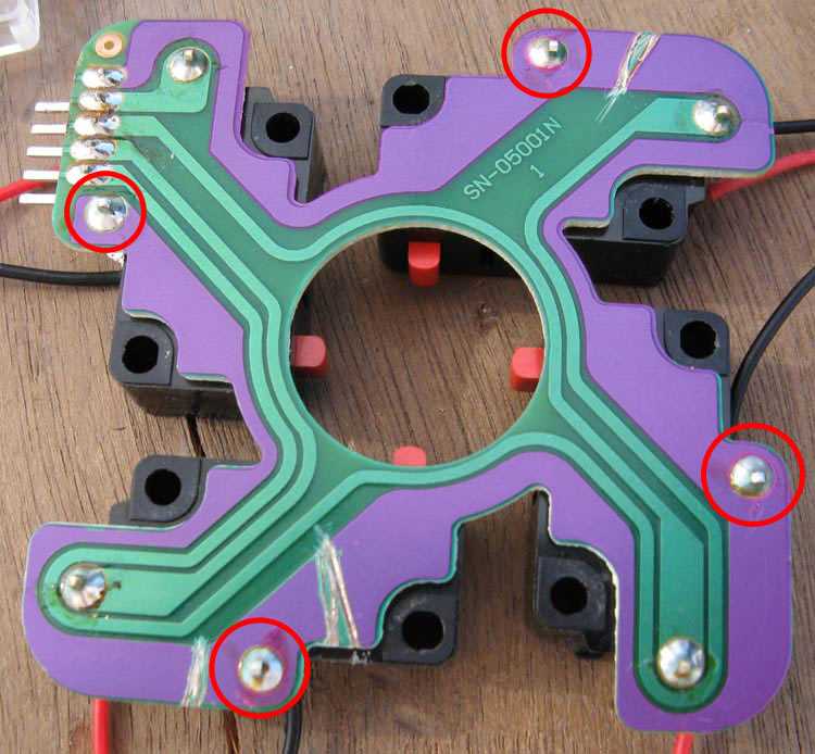
from this site :
http://m.chupon.free.fr/?page=article_detail&id=modder-un-stick-arcade-mayflash-en-full-sanwa
should help you.
good job but Mayflash it is not microsoft and use common ground :lol:
http://forums.shoryuken.com/showpost.php?p=7030708&postcount=302
As you can see from my post, the newer Mayflash PCB (2009) isn’t common ground. The one in that French link is though so it’s actually hilarious they cut traces, etc.
Stupid of me not to mention which type I meant for the stick, its a JLF. I got it done anyways, thanks.
I just finished my Mayflash mod today after receiving my Lizard Lick order this morning. My Mayflash has the 2009 pcb revision.
I used the same methods as seen in these images from other people’s mods to connect button wires to the pcb:
http://kowal.itcom.pl/foto/modUFS-OKB2.jpg
And bottom mount the JLF:
http://kowal.itcom.pl/foto/modHSC4EX-15.jpg
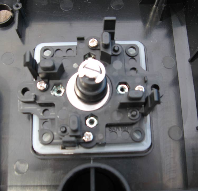
The shaft ended up being a little shorter than the stock stick but I’m fine with it. I also used the stock Omron switches to avoid having to cut the ground traces on JLF pcb.
It’s because the tuto’s author thought that Red=+VCC and Black=GND
do you have some photos of this connector? where can it be found? I think I may try to do the same kind of connector using some aluminium foil and adhesive tape.
Oh god how do I unscrew this balltop? >_<
Been trying for a while and the damn thing hasn’t budged.
My stock one wouldn’t unscrew either. I eventually just busted it off and got on with the day. Have you tried tapping the underside of the balltop with a hammer and then unscrewing?
I found that given the 2.5mm pitch of the Mayflash PCB the JST NH connectors are the perfect choice:
http://img37.imageshack.us/img37/3168/s2020179x.th.jpg
http://www.jst-mfg.com/product/detail_e.php?series=182
It’s the same connector family as the 5-pin header Sanwa and Seimitsu use for their sticks.
Alright, I need all of your help! I’m stuck between this two pictures for my Mayflash.
Blue: Random picture I found that I had my friend turn for red to blue (My favorite color)
http://i32.photobucket.com/albums/d39/BR_aka_Evenstar/Untitled-2.jpg
Then we have Hellboy, my favorite comic book character.
http://i32.photobucket.com/albums/d39/BR_aka_Evenstar/hellboyone.jpg
Now all I have as in parts Dark Hai buttons and thats it. Which one you guys think would look good?
I used connectors from an old pc USB 1.1 adapter and the wires that were connected to it.
http://i264.photobucket.com/albums/ii196/lilaznkid265/th_usbadapter.jpg
The dark gray wire on the far left of the left connector is not used. For the ground I soldered the white wire into the right connector that you see on the far right.
http://i264.photobucket.com/albums/ii196/lilaznkid265/th_connectors.jpg http://i264.photobucket.com/albums/ii196/lilaznkid265/th_connectorstopview.jpg
And this is my mod completed two days ago. I decided not to use the piece from the stock stick as a spacer to bottom mount the JLF, which is the method used in the French guide, because it turns out I wasn’t fine with how short the shaft was. I still plan on spray painting it and applying artwork sometime in the near future.
http://i264.photobucket.com/albums/ii196/lilaznkid265/th_completemayflashmod.jpg http://i264.photobucket.com/albums/ii196/lilaznkid265/th_completemayflashmod-1.jpg
Yeah, the balltop is a bitch to unscrew because of the glue used. My brother was able to remove it with a flat head screwdriver and brute strength alone, but not without severely stripping the head on the stock stick and leaving his hands really sore. I’ve read from others that you can wrap something around the shaft like a paper tower and use a clamp or pliers to hold the shaft in place while you unscrew the ball. You can also wrap a rubber band around the ball for a better grip. I hope that helps.
Use the first one for sure, looks hot.
And thanks for the balltop suggestions, still haven’t removed it yet though. :\
Very nice, fokkusuhaundo! I wish I planned that far ahead when doing my own mod.
If you’re trying to get the stock stick off, you can try removing the e-clip. Just take a flat screwdriver, push down the actuator and pry the e-clip out. Once the e-clip is off, it should just fall apart.
thanks. very clean. do you mind adding a more detailed photo of how you wired the joystick ?