If I dont want to use the triggers then can I just unsolder the trigger buttons and just leave the solder points empty?
no, you have to use resistors if you remove the trigger pots
So if I leave that little black square thing (with the white circle) soldered to the board I shouldn’t need resistors?
u can leave em on, but for triggers they won’t work as buttons. Doesn’t matter if you’re not gonna use them of course. You can also do the same for removing the thumbsticks.
http://img135.imageshack.us/img135/4442/360pot1asg6.jpg
http://img135.imageshack.us/img135/360pot1asg6.jpg/1/w431.png
http://img217.imageshack.us/img217/8148/360pot1bzg3.jpg
http://img217.imageshack.us/img217/360pot1bzg3.jpg/1/w512.png
Here I removed them and put them on other side cos I wanted a flatter side on the front. Center them then hot glue them so they don’t move.
I ripped off one of the pads while soldering, the left trigger, 3rd solder point on the right (ill post a pic later if you need). Is there any where I can solder to to repair it?
if you follow the traces you might be able to find another solder point.
Pics
Pics:
http://img.photobucket.com/albums/v643/Sephiru/winningrun/pad1.jpg
http://img.photobucket.com/albums/v643/Sephiru/winningrun/pad2.jpg
^^^ The missing pad is the low side of the pot (ground), the middle pad is the wiper and the left pad is the high side. The other trigger is a mirror image of this one.
In simple terms from left to right…
Left trigger: High, Wiper, Low
Right trigger : Low, Wiper, High
Is there anywhere else I can solder to (with a wire) since I’ve ripped that pad off, like another solder point?
You could use the trace going to that lead… its not an easy task though.
Take a look HERE for a good tutorial on working with traces.
On a side note… im not 100% sure about this but going by what Kaytrim said… being that pcb is common ground and you broke a ground for the trigger, shouldn’t he be able to use ground from another location?
It sounds like from your earlier post that you **don’t need triggers. ** In that case, all you need to do on your LT is to solder a 10K resistor between the existing pads. Don’t worry about the lifted pad, you don’t need it for what you are trying to do.
Yep, don’t even need to find a trace or anything fancy. Just take a exacto knife or whatever and scrap away the green part like to the right of the lifted pad. Should hit some metal material and there’s your ground.
nice, thanks
I managed to put the black square thing back on the right trigger, as for the left trigger I’ll do that 10k resistor thing. Thanks for all your help guys.
why dont you just use a resistor on both sides and be done with it. If you dont get that pot set dead center its going to cause issues.
I just extracted the board from a newer style mad catz 4716. Now I have two questions: 1) What’s the best way to remove the plastic analog sticks? and 2) Could someone post a pic of one of these with triggers wired for use? Is that what this is?
I picked up a small pack of 10k ohm (1/4 watt, 5% tolerance if these are important factors) resistors and two 79 cent NPN silicon transistors. Is this everything I need to do the job? Thanks for your help.
I didnt need to use the transistors on my 4716… it worked perfect with just (1) 10k resister per trigger.
-
I usually gob new solder on the joints, then use some solder wick to pull out as much as I can. There’s usually a little bit left so I take a pair of needle nose pilers and grab a hold of one of the “legs” and apply heat and pull at the same time. Repeat for the other 2 “legs” That’s probably the most ass backwards way to do it though since I am not all the great with a soldering iron. Proceed at your own risk.
-
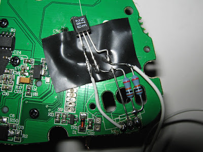
That is the picture I posted of a working one. Just be careful since the NPNs I got were apparently different from normal. The base and collectors are swap so just make sure you look at the diagram on the package and figure out what’s what first.
Yea, thats weird cos I saw your post about that earlier. Thinking I was smoking some crack and wasn’t paying attention, I tried it again on a another “newer” mc pcb with just a 10k resistor. I get the same result as my first try. It kinda works meaning that when I press down on the button, nothing happens. As soon as I release the button, the action comes out. Kinda like a negative edge deal.
Also add that I only tested in SF2HDR.
thats the same effect I was having with the pots still connected. I couldnt get them centered for the life of me so I said screw it. If the 10k’s work for the MS pcb then maybe itll work for the Madcats… and it did.