I’ve not started my build yet because I’m waiting for the parts first. I just dismantled the pad for something to do at the beginning. :wgrin:
I’ll follow your suggestion, many thanks.
I’ve not started my build yet because I’m waiting for the parts first. I just dismantled the pad for something to do at the beginning. :wgrin:
I’ll follow your suggestion, many thanks.
I hate to ask for this, but I’m not having much luck finding an actual photo of what I need… which is… figuring out where the “wiper and voltage” are that need to be connected via 10k resistor are on a Mad Catz Retro stick. I’ve looked at the wiring diagrams, but if an actual photo of what this mod on the Retro stick looks like can be made available… that’d be hugely helpful.
I’ll pay you in positive rep and lots of gratitude. :tup:
Kendrik,
Post a picture of the area and I’ll see if I can follow the traces.
Michael
Will that do?
I found this… where someone was asking if these are the points that the resistor needs to run from… but I didn’t see a response to the poster.

Thanks for being willing to help me out.
Kenny
Is that your pcb? If so, you’re looking at the 2 potentiometers on the back. They need to be removed if you want to actually use the triggers as buttons. The middle of a potentiometer is generally the “wiper” or “signal” terminal, and the other 2 are +5v or +3v, and ground. You’ll need to find someone who’s already measured which is which or use a multimeter to find out.
Yes. That’s my PCB. I’ve removed everything that isn’t in the image.
Thanks for that much.
Kendrik,
I honestly don’t think you need to worry about using transistors on that board. Transistors are only needed on the standard shaped MadCatz pad model 4716. Your board is model 4758.
The pictures that you have linked won’t help me as I need to see the traces that are covered by the pots. Since your board has them removed take a good picture and post it here. I have never seen this board in person so I can’t be of much help without it. It is true that the wiper is the center connection. Your high side seems to be the one furthest from the edge but I can’t be sure until you snap a pic of your board.
I’m just trying to figure out where to apply the resistor, so thank you for your help.
Here are the two best shots I could get. My camera sucks… and I’m even worse when it comes to photography.
Sorry to double post… only way I could get a second image to attach.
Will any 74XX04 chip work for this? For example I have a 74LS04 chip and I was wondering if I would connect it in the same way as per Toodles’ schematic.
Pretty sure it would work fine.
I didnt need to use transistors on mine.
just a 10k resistor on each trigger.
Sorry, I forgot all about you. Here you go…
RT
http://picasaweb.google.com/lh/photo/Mt2L7j61tuTI1ivKZ2S7xg?feat=directlink
LT
http://picasaweb.google.com/lh/photo/U7069iwDmq9YQM3uvD4dIQ?feat=directlink
Damn. That’s so simple. Thanks a ton! :tup:
Something odd I’ve been finding when testing my triggers with SFIV on the 360 is that the triggers don’t activate unless I match the signal to the ground on the actual trigger. I can’t seem to use any of the other grounds on the pad. Is this normal? I can’t find anything in here. If needed, my resistor and capacitor layout is EXACTLY like zombie cpt’s. I’m running 10k Ohm resistors and NPN transitors as mentioned in the thread.
Using a madcatz? I know the standard wireless controllers had issues with a separate true ground for the trigger, but i’ve yet to encounter it on the madcatz pcbs
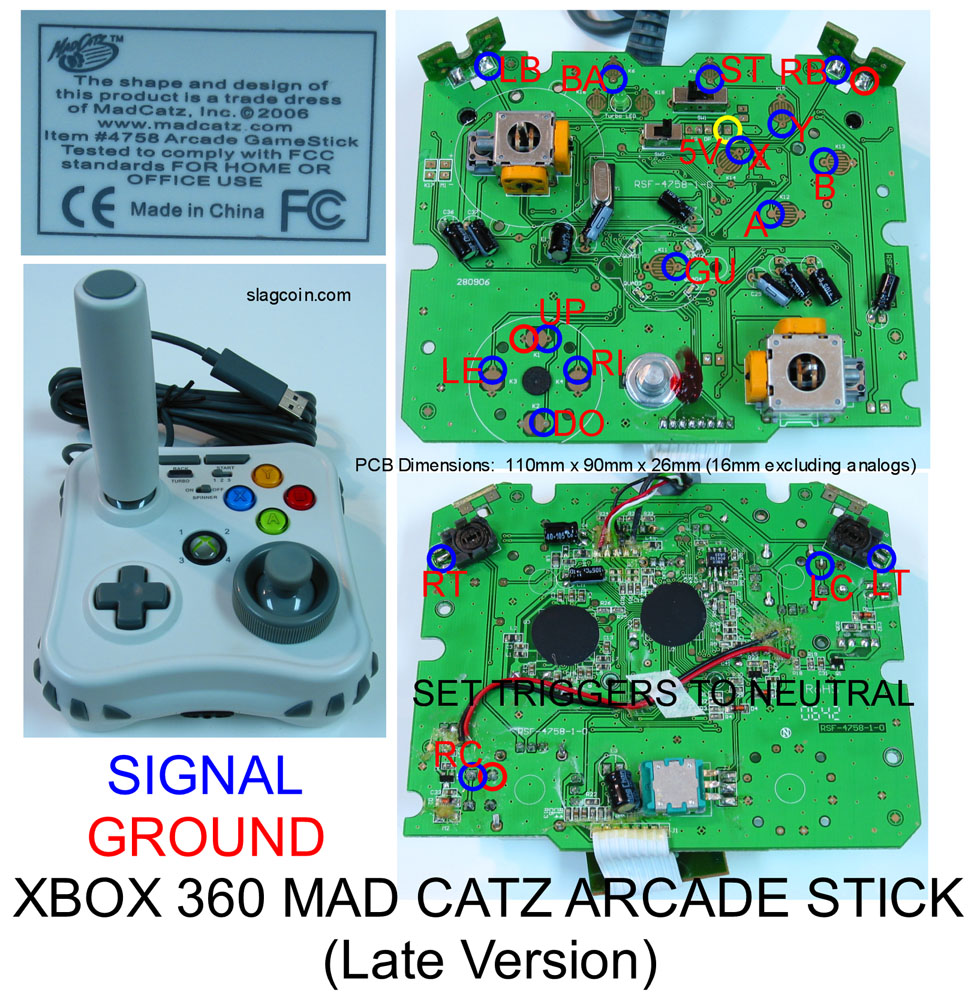
Do you have a picture of the install? It’s a newer MC cg pad? Only the newer MC pad needs this, the older MC cg pad and the retro pad(which I posted a picture of for Kendrik) just needs a 10K resistor.
Also, are you sure the E, C and B on the transistor are like mine?
I don’t know, I need to do one of these tonight so I will see how it goes and let you know if I remember to.
using the same transistor + 2 resistor method for the triggers that have been discussed earlier in the thread, I today finished work on my MadCatz xbox (wired) controller – the 2008 version.
the entire process would have been very easy, but somehow I managed to rip off the middle pad for the left trigger. finding another place proved to be a time consuming pain, but I eventually found a place that wasn’t too crowded to allow scratching the surface and soldering to that oh so very tiny wire. I’ve a decent bit of experience soldering electronics from college (computer engineering major), but I went into this a bit rusty – graduated in 2007. Nonetheless, it’s not something that even a first timer couldn’t do if they have patience and the right tools.
don’t make the same mistake I did there. 
the new spot i soldered the LT wiper too (the purple wire heading towards the center)
and the finished board after connecting to terminal strips and gluing:
checked every button after soldering and after gluing by connecting it to my laptop and using the ‘test’ tab in the controller properties, as many others have shown/done. it helps immensely – that, and a digital multimeter. also, I would NOT use your xbox as a test bed. if you accidentally short the controller, it will red ring your xbox. i’ve accidentally shorted it when connected to my laptop, and nothing has ever happened. not that I ever recommend someone shorting anything, but just sayin…
going to work on my arcade stick box/shell tomorrow (1/2" MDF mostly, with 1/8" HDF and 1/8" lexan sheet as a top)…and then eagerly await the arrival of my ls-32-01 and OBSN buttons!
Good work mang but you know you could’ve save yourself some work. You didn’t need to daisy chain the ground on the pcb like you did unless there was some reason that I am unaware of.
Good looking out on the testing thing though, never though of that.
okay i know this is the wrong place to ask and im sorry but im not getting any help at all with this and with recent posts in this thread ill risk being flamed and ask again
im trying to wire triggers witht he wired xbox 360 controller but i cannot find info on how to do it
i keep getting conflicting information as well as no schematics, detailed instructions or even the right guidance on how to do it
this is what i am deciphering from what i see on here but i get told otherwise alot
1 resistors are only used when deleting the pots for the triggers and NOT using them in a controller
2 if using the triggers as buttons you only need to wire to the T## contact then the other side to ground leaving the pots in place
3 i have no clue what “set triggers to neutral” means as i see it in every PCB pinout picture i see
i know i should check the xbox thread but in all honesty none of the posts in there helps