your vid shows that you hooked up the wrong OUT lines to the wrong LED’s. probably because you had the metal plate upside down and forgot the buttons are in the opposite order… thats why the screen saver is going in the opposite direction. also check the jab LED… you might of had both the prongs connecting or accidentally linked the LED’s sig and ground together when soldering. Its an easy fix if thats the case just cut the bridged connection and give it a little separation.
looking at it also does your screen saver mode always start at forward? 2K cause if thats the case you really wired it wrong… it has always started on Jab “1P” going in a clockwise motion
I just completed a pretty cool-looking inverter-less mod on the custom stick I built when SF4 came out. Video to come when my cousin wakes up and I can borrow his camera, but I did 16 damn LEDs, 8 light-up on button press, 8 with the different joystick directions, in red and white. It’s looking pretty cool, but there’s a damn rats nest of wiring there now, instead of the neat setup I had with only signal and ground wires to worry about. I had a couple questions, though:
The LEDs assigned to my RT and LTs constantly glow when the XBox is turned off, which I’m assuming has to do with current flowing through the hacked triggers (I’m using a Madcatz Retro stick PCB). Is there an easy fix? I’m not up to any huge changes after all that wiring.
Also, I’m noticing some dropped inputs, and I’m assuming it has to do with the controller not being able to properly power all of the lights. Would I insert a battery pack thusly? http://img443.imageshack.us/img443/9646/diagramw.jpg
I’m not sure what the benefits of the hex inverter diagram are over this setup, but I fucked up on my first attempt at building that tiny breadboard, and I at least managed to get it working this way. I’m not sure I have steady enough hands for this. :sad:
I’d appreciate any help! I finally got this working after over a year, and I’m gonna show it off at my first tournament on Sunday!
Well, I tried the above, and I think it fried my PCB. Can someone please weigh in on the CORRECT way to add a battery to an inverterless setup? I’m gonna have to hack another pad tomorrow–thank god for barrier strips.
my first recommendation anytime playing with power supplies and such (VCC + GND) use diodes. really, its that easy, but often overlooked. prevent the backflow of anything.
now that being said, the likely hood that your pcb is fried is maybe. check you battery as well, makesure you didn’t short it or drain it or something
Rollie Pearl Buttons look so nice with LEDs inside them
I just got in my Rollie Pearl push buttons to go with my Seimitsu Pearl pushbuttons that I put inside my Chun Li TE. After I got the LEDs into my the pearls I was pleasantly surprised at how soft and incandescent all of the plastic took to the light. I highly recommend that people use at least the white versions of thes buttons in future LED mods. They look really nice and more even.
This is a comparison shot to how the sanwas that used to be in there looked. I really didn’t dig the radial light pattern on the sides from the inner walls of plastic blocking light.
Anyone can tell me if I can use Toodles LED board with a PS2 PCB? I’ve set up my Arc Eyes for common ground and have the ground of the LED leading to the GND of the LED Controller. The VCC for the LED board is connected to the 3.3V of the PS2 PCB. I have a “Red” signal wire coming out into JAB_OUT. JAB_IN is connected to the square signal and I also have a ground going from PS2 board to the LED Board (for testing purposes). The LED Board GND now has 2 wires (LED GND and PS2 GND) connected to it. However, when I plug in the controller, the Arc Eye weirdly pulses green (weird) on one LED and a very faint red on the second LED. What could I have possibly done wrong?
Ok, having a bit of an issue. I’ve got the FG Widget board, and Ultimarc Ultralux pushbuttons. Board is all done up, buttons are installed. (had to cut some of the plastic from the TE to fit the buttons, as the microswitches are on the bottom.) My main issue is that I can’t find a diagram showing how the Ultralux buttons should be connected to the board, I.E: what is the ground on the buttons, etc. I am completely in the dark here, my buddy who usually helps me with these things is out of commission right now with an injury.
hey there, just to get a better understanding.
are you using the Ultimarc Ultralux with the RGB LED? the 4 wire harness? if that is the case, you are SooL and my recommendation would be to use their LED driver board.
if you are using their single color solution it’s pretty straight forward. the LED houseing has a +/- on it. should be easy from there.
on the LED goes to the matching *_OUT screw terminal on the LED controller
The microswitch prong labelled ‘NO’ goes to the *_IN screw terminal on the LED controller (which should also be connected to the button’s signal line on your game controller pcb)
The microswitch prong labelled ‘COM’ and the ‘-’ on the LED both connect to ground together, usually a daisy chain connecting all of your buttons, that connects to the GND screw terminal on the LED controller and a ground point on the game controller pcb.
The microswitch prong labelled ‘NC’ doesn’t connect to anything. Leave it alone.
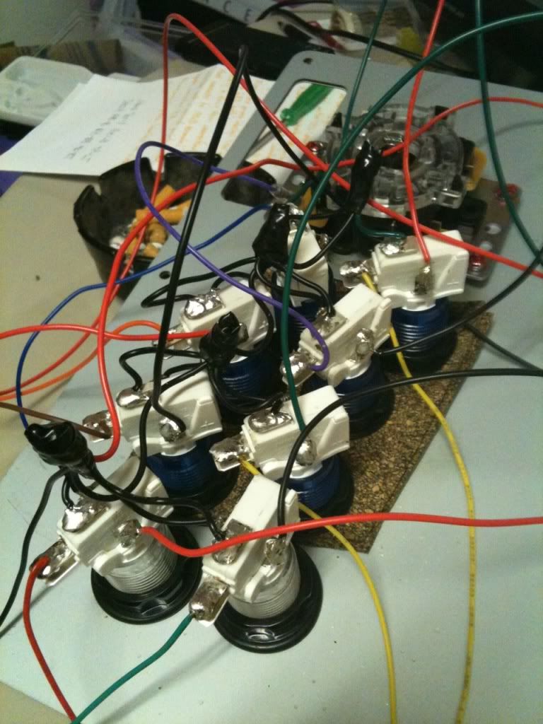
Ok, so I have hit a roadblock. The LEDs light up, but the buttons do not respond. Here is a picture of how the buttons are wired up.
Toodles said:
The microswitch prong labelled ‘NO’ goes to the *_IN screw terminal on the LED controller
(which should also be connected to the button’s signal line on your game controller pcb) ?
where on the pcb am I connecting this? Am I right in assuming the terminal block connects to the signal line and can therefore be used? If anyone can explain this, or maybe post up a picture that would be phenomenal…I’m so lost right now its not even funny…
Wow, you actually fit IL/HAPP buttons in your TE? That’s an accomplishment. I can’t tell you how to wire them properly but I can tell you that I think you used a tad bit too much solder which can be a problem in its own right.
I also noticed that the third button from the left on the bottom row has some exposed wire and might not be making a good enough contact.
currently, I have the ‘NO’ lead connected to one of the two plugs on the terminal block and the other terminal block plug connected to the LED controller. The controller is just floating right now, haven’t secured it yet.
How am I supposed to have the buttons connected to the pcb? Was I right in going through the terminal block? do I have to run two wires from the microswitch lead? Please help if at all possible.
Yeah, that’s not gonna work. Look at the little terminal block; each color pair has one terminal closer to the back wall, and one terminal closer to those little ribbon cables. The terminal closer to the back wall is the connected to ground in the terminal block. The one closer to the ribbon cable connectors are the actual signal. That one needs to go to both the ‘NO’ tab of the microswitch, and to the *_IN screw terminal on the LED controller.
