Yeaa, listen to Toodles for sure. I learned those first two lessons the hard way the first time I used mini-DIN. I’ll also add that you should be careful when pushing the crimp pins onto the mini-DIN pins. I snapped one pin off at some point and felt like a careless brute.
Here’s the cheat sheet I used (I think it’s mini-DIN standard, for what that’s worth), in case anyone wants to just use it:
Pin 1: G
Pin 2: A
Pin 3: B
Pin 4: C
Pin 5: D
Pin 6: E
Pin 7: F
Pin 8: V
Toodles, what kind of crimping tool did you use for the crimp pins? Searching Digi-Key’s site for an appropriately sized crimping tool wasn’t very helpful. I just used needle nose pliers–it worked pretty well, but I’d like to be able to get a tighter wrap on the wires.
Thanks, now to find some short barrel din connectors that look good mated. They call the connectors I was talking about “locking” connectors, didn’t see any I liked online though, all long barreled or over sized.
I think the correct term for the little floppy style connectors I’m looking for is friction locking PCB header. Maybe MarkMan can get us the supplier/part Madcatz is using?
I just use needle nose. Tin the wires, and lightly touch it with an iron after the crimp is on. I have a modded AES stick with a long cord with female miniDIN on it, and will make a cigar box stick with a female miniDIN on the box when I get back. Sometimes the crimps are annoying, but I just feel I can trust the miniDIN connection a lot easier than I can RJ-45’s.
So I’m thinking of running LEDs inside my TE (ordered a clear plexi from Tek-Innovations) to be powered up whenever I plug in my stick. Not to light up as I press the buttons, just to light up the insides of the stick when plugged into a console.
Ideally, I could use the top 11 rows of the MC Cthulhu for my buttons (and all applicable spots on the Imp), and use the ground/VCC on the screw terminals to power my LEDs/resistors, correct? Or, is that kinda how you’re supposed to do it?
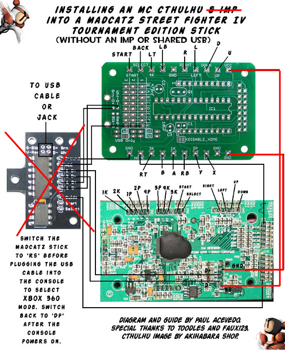
My plan is to have all the wires lead to a RJ45 jack, including for usb, and based on all the tutorials, it seems like this would work. I figured I’d throw the diagram up to make sure, and so I didn’t damage anything through the install.
I’d wire the ground from G (yellow), D+ to E (Purple), and D- to D (Blue), instead of the designated spots. If my thinking is correct, the wiring should run through the imp, leading to the letters shown below.
Pin - Board - Use \ Letter
1 - Imp - Ground \ G
2 - MC - A
3 - MC - B
4 - MC - C
5 - Imp - Data - \ D
6 - Imp - Data + \ E
7 - MC - F
8 - Imp - VCC
Thanks for any input, and thanks for the diagram Bomberman.
Final edit: I think I found the answer in the FAQ of the official cthulu thread, yes it should work, but I’ll leave this up because A) I could be wrong and B) it could be useful for others.
New here but had some questions. I just bought the original xbox360 Street fighter iv tournament fightstick and am planning to mod it to work with the ps3. I am planning to buy the Chimp Assembled with USB Jack from lizardlicks for $50 (why is it $5 more with the usb jack when the one without the usb jack is $45 and the usb jack is $3 if sold separately? Is it different somehow or is it wiser to get the $45 chimp+$3 usb jack?)
Anyways, back to my questions: I know prophecy asked a few posts ago but, Do I need anything besides the Chimp board to install it onto my Fightstick? By anything, I mean extra wires, tools, or all of that stuff on the first page. The only things I have are the soldering iron and tools to open the stick.
Are all the wires going to be from the stick and I’m just redirecting them onto the chimp board by following the “Installing Chimp in MadCatz XBox360 TE Stick” guide?
One last question:
What is/Where can I get this octagonal(?) gate to replace the square gate? Is it those restrictor plates or mounting plates on lizardlick? I’m sorry if all of this has been asked but I am a complete noob/newb with fightsticks and would just like to get a list of things I need together so I can order everything at once.
Just wanted to drop a quick thanks to Bomberman for the detailed tutorial, and big thanks to Toodles for the impressively easy-to-use boards and documentation. After quite a few headaches over the past few days, I managed to get all the kinks worked out and get a successfully dual-modded SE Fightstick up and running (fingers crossed that it stays that way).
I’m holding off for now on the much more involved RJ-45 mod (or perhaps mini-DIN?), but now I actually believe it’s possible for a hack like me. I haven’t done much soldering work since I was a kid (working on RC cars), so this was a bit of a harsh refresher course!
I just have one simple question. The first few post have enough information for me to do the mod for a MC Cthulhu + Imp mod to my TE stick except one piece of info is kinda missing (because its probably so obvious but I want to be sure) there is no clear instruction on how to wire the buttons and joystick.
The pinout is labeled on the pictures for the TE board and the Cthulhu but the wire route is not. I am guessing that you leave the TE board connected as per normal via the ribbon cables and then just solder “extensions” from the back of the TE PCB to the correct button inputs on the Cthulhu board? Like a daisy chain? Do we have a diagram of the way the TE buttons would connect to a MC Chthulhu for proper button placment?
I have lingering thoughts in the back of my head from when I did my last mod that had certain warnings about wiring 2 PCB together, but I do not recall it being an issue with he buttons, it was more to do with the common ground I think, so thats why I just want to make sure.
I may be a new member to the site but I have visited here regularly. I usually look at SF4 stuff and modding arcade stick stuff.
Anyway, last year I spent a couple months studying and reviewing this thread to learn how to dual mod my SE stick. I made sure to know what the heck I was dealing with before I even bought the parts (cthulhu and IMP chip). I managed to barely get it working right before evo2k9. The wiring was janky. I got confused in the guide and ended up wiring things to spots that made sense to me. The main problem with my stick was that the guide/home button wouldn’t work, and it was really difficult to get my stick operating on a PS3 if someone had plugged in another controller prior to or after my stick was plugged in. Almost a year later, I decide to revisit this thread for further reference and do things right. I rewired my stick exactly how it’s shown in the diagrams, but now my stick doesn’t work at all. No devices are detecting it. However, I did melt some wires together on accident. SO… my weekend project is to take out all of those wires, and re-do the entire thing from ground up. I will be following this guide “to the T” and hopefully it works. I thought I should let you all know, thinking it would help if I came across any problems over the weekend. Any advice would be great even though the guide apparently covers everything I need to know.
Just spent the last few hours putting it all together… Did everything the guide shows. I’m convinced my board(s) are fried. There is no response when I plug it in to my pc, ps3 or xbox.
I have a question. I have a Cthulhu and a TE stick, no Imp at the moment. The Cthulhu works fine and all but the 360 portion is having some problems. I’ve checked through the thread and saw it mentioned briefly but with no solid answer.
When I plug in the 360 USB cable to my computer one of the turbo LED’s goes on, along with the 4th player ring on the guide button. I’ve checked for any possible shorts and I don’t see one. Any help is greatly appreciated.
I think the original idea of a Cthulhu + Imp is a great idea for the 360 TE stick. You wont have to make a new hole or have a 2nd cable for the PS3 connection.
However since I want to use the MC Cthulhu and will be making a spot for the RJ45 jack. I see no reason why I cant make a RJ45 --> USB connection for the PS3 and not use the Imp board. This should lead to a cheaper and easier mod with less room for error/problems.
No need for a toggle button for mode just plug in the correct cable.
So here is what I think I am going to do, will somebody please verify that this will work.
Connect the VCC from the MC board to the 5v on the TE
Connect the Ground from the MC board to the Ground on the TE
Connect the button signals and joystick signals from the TE to the MC board (I need to figure out what button goes to what spot but I think thats posted somewhere like on page 3 or 4 of the mod thread)
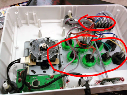
As for connecting the buttons/joystick it should not be a problem to connect them from the terminal area or directly from the buttons quick connect instead of from the PCB correct? Like where I circled in this image below (yes I know its a SE stick just an example)
I’d like to know the answer of this question too. I’m almost in the same situation except im doing this on a ssf4 TE-s. And I’ve only ordered the MC Cthulhu assembeled. I haven’t purchased the IMP mainly because this stick’s main purpose is to be used only at home. So I’m building this w/ the intention of soldering as little as possible.
What I would like to know is;
For the Buttons: I was thinking of soldering the signal wires from the MC Cthulhu to the base of the Quick Connect where the copper wires from the TE are crimped. I’m trying to avoid directly soldering onto the TE PCB. Will this work?
For the Joystick: Is it possible to cute the 5 wire harness in the middle. Place a small terminal barrier inside, add on one end both the wires from the TE PCB and MC Cthulhu, and on the other end insert the wires that will lead to the 5-pin.
I’ve been practicing soldering onto some blank perforated boards for about 2 weeks, so obviously im not too confident with it (Mainly its that I’m not confident in soldering multiple joints that are very close to each other.)
I’ve read Bomberman’s excellent guide, but I’m still a bit confused as to what board I should buy.
I wanna dual mod my SE stick, but since I’m a complete beginner when it comes to soldering, I’d like to keep it to a minimum. I’m planning to buy an assembled board, but I don’t know if I need the Imp or not.
Basically, I don’t care if there’s two cables hanging out the box, as long as it works. If I’m correct, I only need an Imp OR a switch to change between XB/PS3? So I guess the “impless” version doesn’t work if I wanna use both systems without installing a switch?
Sorry for the confused questions.
Thanks in advance.
Good idea with the barrier strip, you could even do that with the buttons (just make sure you get the signal wire and not the ground) I feel pretty confident in my soldering skills after a bit of warm up I get the hang of it, but I have not taken apart my TE to look at just how small the board is yet. Since I was only able to get the fully assembled MC Cthulhu unit I would kinda like to make use of the screw terminals rather than try to solder on the bottom side. But I already bought the recommended 30awg Kynar wire and will give it a shot. If I can use it well the result will be much neater looking than the larger wire all screwed down to barrier strips.
But then again what does it really matter? Other than the pictures you may choose to post of the mod nobody will ever see the inside, so all that matters is that it works, and the barrier strips will make it a lot easier to fix something should you make a mistake like button layout or to add maybe a 3rd pcb or something later in life.