Missing Person, you’ve pictures of your work?
forget it, i just destroyed the pad trying to fix it.
i hate these pieces of shit. they never. fucking. work. when. i. try. to. hack. them.
easy as pie!!! if u cant hack this pad after reading this tutorial…u might want to buy a soldered up pcb …thanks guys for the input i learned alot by this thread!
Upas, just wanted to express my appreciation for your guide.
I hope you don’t mind, but I’ve re-used and annotated some of your PCB pics in a related mod I did on the VSHG. Info and pics can be had here: VSHG PS3 and XBOX 360 Switch Mod
Cheers.
I managed to dual mod my stick thanks to your guide. All I have to say is OMG, it is not an easy task.Extremely time consuming, but well worth it. FYI if you break a connection point on the madcatz pad, just solder onto what ever bit of connection you have and use a #2 pencil to scribble between the connection point and the carbon tracing, then cover it with glue. Works everytime.
I had my joystick wired for the xbox1, so I rewired it for the 360 without looking at any tutorials, and ripped off the pots. The stick worked fine then I decided I wanted a TE and my custom has just been collecting dust, I went to plug it in so my gf could play with me and there’s some really weird shit happing, like buttons randomly don’t work, or go off on their own.
Is that something that would be caused by not having the pots connected and set to neutral? and if so is there a workaround to disable the triggers because I am not sure if I kept the pots or not.
If you have this exact PCB (GAM4176-1 VER.E), then the triggers are active high:
Stupid question probably, but would any of these inverters available locally at Fry’s be able to do the job? Or are they not the correct series type, or something?
Alrighty, I’m having some trouble with the triggers in a dual mod with an MC Cthulhu and Imp with only the right trigger hooked up. Right trigger works fine in ps3 mode, but the button does nothing in xbox mode. As far as I can tell, everything is hooked up correctly, nothing is shorting, and I’m fairly sure there are no cold joints. Any ideas on what I should be looking out for?
Popular to use, any 7404 or 7414.
So I take it that one will work just fine then? Good to know, thanks.
Oh yeah sorry, I was referring to the 7404 and forgot to specify it. Thanks!
For the 2009 Madcatz 4716, what is the harm in just removing the pots if you don’t want to use the triggers?
I hacked one of these and although the pots looked as though they were set to neutral when I checked with my PC, when I used it with my 360, it was as if the RT trigger was always pressed down.
I had already glued the pots to what I thought was neutral, so after this, I just desoldered the pots and took them off. I don’t have any issues, but I’m wondering if something is going on that I can’t see.
Again, why does everyone say that you can’t simply remove the pots and leave it at that?
Not having the pots on there makes the pad think the triggers are always pressed. You can either replace the pots, or you can solder a resistor between the wiper and low pads of each trigger.
How much resistance? 10 ohm is good?
I used a 10k, it needs to be a higher value resistor, I’d stick with at least like a 4.7k to be safe.
Thank you sir. I may do this. I haven’t had any problems thus far though, and it’s been 4 months or so. I guess it’s better safe though.
I know exactly what you mean. Recently padhacked one of these for a friend, and accidently ended up tearing off the silver contact point when trying to remove the pot. =( Spent half an hour fretting and trying to find another solder point I could use, but couldn’t find one. I’d remembered hearing “It’ll always be pressed”, but we plugged in the partially hacked controller and found that everything worked just fine.
Went into BlazBlue / Garou / Battle Fantasia (and a couple other fighters) and none of them were acting like that trigger was being pressed, nor was the X-Box home/guide/thing.
Point being, it’s been a while now and we haven’t seen any problems arise. (Aside from 2 less buttons) I guess it’s better safe than sorry to use the resistors in the first place, but I have yet to see any real negative effects from it.
Okay, I think I am going to go insane if I don’t figure this shit out.
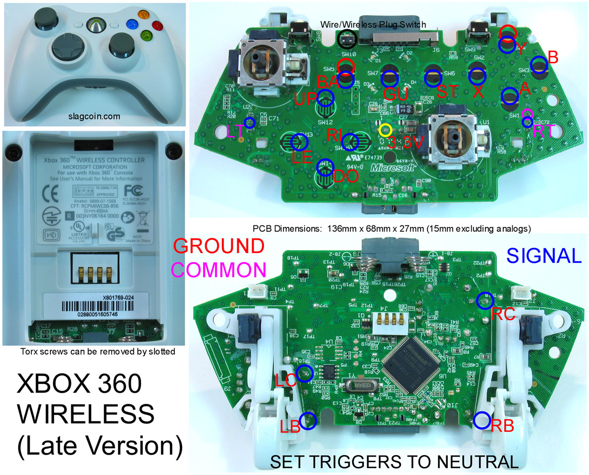
So I’m using an NTE7404 hex inverter on an official new-revision Microsoft Wireless 360 PCB (shown here; it’s the same exact situation as the Madcatz controller used in the tutorial in this thread, with a common high-line for the triggers/analog sticks, and a common ground for everything else), and I am getting some really weird results. I have followed the instructions exactly, and I am using 10k Ohm 2% tolerance resistors for the voltage line going into the inverter. I’ve also neutralized the two analog sticks with two 4.7k Ohm resistors per pot, as seen here, but that shouldn’t affect anything having to do with the triggers (I think). I have double-checked and resoldered the entire inverter to see if there were any bad connections, and I can’t seem to pinpoint the problem. Two things in particular are happening:
1.) The Guide button, when grounded (pressed) activates just fine, but it also activates RT (when exiting the Guide menu on the dashboard, the categories scroll down quickly as if you pressed RT). Otherwise, it seems to work just fine.
2.) The RT and LT connections from the inverter aren’t working. If I make a connection from any of the ground pins on the inverter to either of the “output” pins (1 or 3), nothing happens. If I happen to connect the ground to pin 2 or 4, however, nothing will happen until I break the connection; the “button” then activates, either RT or LT.
I don’t have a wireless 360 adapter for my computer, so I can’t go too in-depth with investigating if/which buttons are being held and whatnot. All of the other buttons and the D-Pad work just fine, though. I’ve done padhacks in the past with ease, so I’ve never been this frustrated with something that should be very simple in concept. I’m going to scour the entire PCB to see if there are any rogue little fragments of solder/metal that could be causing a short or anything, but I doubt that’s the case. Can anyone help me out? I can provide pics if necessary.