Bump. I have given up for now so the inverter is packed away for a while, but using a 10k Ohm resistor from Low to Wiper works, obviously. I won’t have any pictures until at least Monday. What gives? Was my theory completely wrong about the neutralized analog sticks not interfering with the triggers? Did I completely overlook something in the guide? It’s driving me nuts.
guys i’ve accidentally chipped the 3 solder point of the left pot. Is there an alternative solder point for this? I wont be using the triggers BTW. Or is it okay to leave it like that?
Is there any alternative points for the wipers (both) and Low for the left trigger on the madcatz 08/09?
I must be completely inept, I broke off the contacts when trying to take off the pots.
You can trace the contacts, strip the coating, and try to solder to the copper underneath.
Hey SRK!
I tried to do this today for my cousin… seems I’ve run into a bit of a pickle.
I took the PCB out of the shell and plugged it into the computer… it loaded fine. Then, using a Sanwa button with two wires i touched each respective GROUND and SIGNAL and got my cousin to push the button, checked the computer, and verified that the registration was there. We then turned the POTS for LT/RT until Z-AXIS was in the middle (as stated in the guide) and glued them down.
Here is where things went bad… when we began to solder.
After soldering lead SIGNAL wires for X, Y, A and B, we decided to go back to the computer and ensure everything still powered on. As it stands, Windows XP says the “USB Device plugged in is not recognized”. The 4 lights around the GUIDE button light up immediately after plugging the device in, and then immediately turn off.
I AM GUESSING this is a short?
The picture below shows the XYAB that Upas soldered:
http://farm5.static.flickr.com/4045/4278483162_343aa86cd3_o.jpg
On mine (which I will take high res pics tomorrow morning and post), where those TWO arrows are that I’ve drawn … those leads, are they ground and signal?
Because the area i’ve circled, there is solder basically touching those two leads together, where i’ve put the wire…
Sorry for the crappy MACRO, my cousin took the shot… anyways… the below pic is what I was describing, WITHOUT the wires (i removed them as I’m guessing its the solder spilling over that’s shorting the ‘leads’ that i referred to in the other diagram?
http://farm5.static.flickr.com/4009/4277752649_ffafb4ebc0.jpg
I’m guesing this solder is bridging the SIGNAL and GROUND which probably explains why the controller turns on for a brief second, then immediately turns off (in the 360) and gives “unrecognized” status (on the PC)?
I ask this now because I can’t go back to my cousins house until next Friday and I’d like to be prepared
That is one line.
It is Signal.
The dark green is nothing.
It is what between those lines, the Trace.
Thakns JDM. I guess its time to clean up the solder and start over…
Cutting off this thing ->
(since we are doing dual setup, we needed to trim the wires as much as possible) wouldn’t have caused it to stop working, would it? Originally we thought it had something in there important but we cracked it open and all it was a giant ball of lead or something resembling that…?
http://farm5.static.flickr.com/4055/4279415644_0c24efe681.jpg
Because 5 wires from from the back of the Madcatz and where we trimmed there’s only 4 wires leading…?
http://farm5.static.flickr.com/4024/4278675943_fbc388fe73.jpg
The giant ball thing is a ferrite bead.
It just suppresses high frequency noise.
Thick black is Shield Ground.
You don’t need it.
sorry but is this for the purpose of making a custom joystick?
Yes.
Or to add another Console support to existing Arcade Stick of different Console.
thankyou, i am just about to finish my custom vewlix cab and was wondering how to hook up the sanwa parts to my xbox 360…
it worked!!!
thanks you Upas, JDM and everyone else for your patience and assistance!!!
Hey everyone!
I’ve been modding for the past couple of days and it seems to have gone smoothly. Everything was going well and we started putting the case back together and hot glued all the components. Once we started playing with the fight stick, it would randomly switch between it’s actual function (lk,lp,mp,fw,fp,rh) and would somehow activate turbo of that button coming out with no input within the game (for the xbox controller.) as well as randomly turning having the controller turn on and off. Now when playing on the PS3 PCB it works perfectly fine - but the mad catz controller (and xbox) seems to be giving me and my friends difficulty.
we alivated the random off and on that the controller was suffering by changing out the the dual throw switch and soldering onto the switch itself, but it still has the random turbo activation and input drops.
Any help would be greatly appreciated!
My set up is a
TE PS3 version mad catz fightstick
mad catz 4716 fight pad. I don’t know if there’s anything else worth mentioning :o
I’ve tried this hack twice now but have run into the same problem both times. I get random activation of the Guide button, with no evidence of any shorts anywhere. Sometimes the console will turn on when I plug the controller in, and sometimes it’ll activate the console later. Of course, when playing, it’ll activate the Guide thing at random.
On one of the controllers I tried cutting into the PCB to make sure there was no contact between ground and signal, but I still have the same problem. I’ve tried removing the wires time and time again, but to no avail. I find it odd that I get the same issue with both controllers. Everything else works fine. I leave the triggers on because I don’t feel like messing with them in any way, and I just need a six button layout. The last controller I tried looked slightly different, with different colours on the solder points, but otherwise looks to work in the same manner. I’m new to soldering like this, but the points are huge and, again, I find it odd that the exact same button has issues on two different attemps. I must be missing something here. Any help would be much appreciated.
Did it. Twice. Works like science.
Great guide.
Is it possible to connect the guide button to the turbo button on a ps3 TE stick?
Thanks.
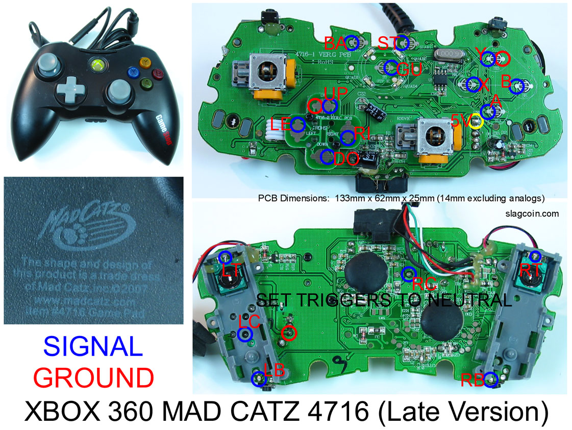
Anybody know where the +5v contact is on this PCB? I have no multimeter…
enjoy!
Thanks, but that’s the 07 pad. We’re talking about the 09 pad, it’s a bit different.
Comparing the two boards, though, I think it might be the contact outlined in red.
http://i2.photobucket.com/albums/y12/hadokn/DSCN0497.jpg
Anybody confirm?
just look on the back to where the red wire is soldered, that’s the spot.
I think you’re pointing at the right one though.