Lexan .093 to thick to fit snap ins for clear panel artwork?
AJtheMishima, nice work :tup:
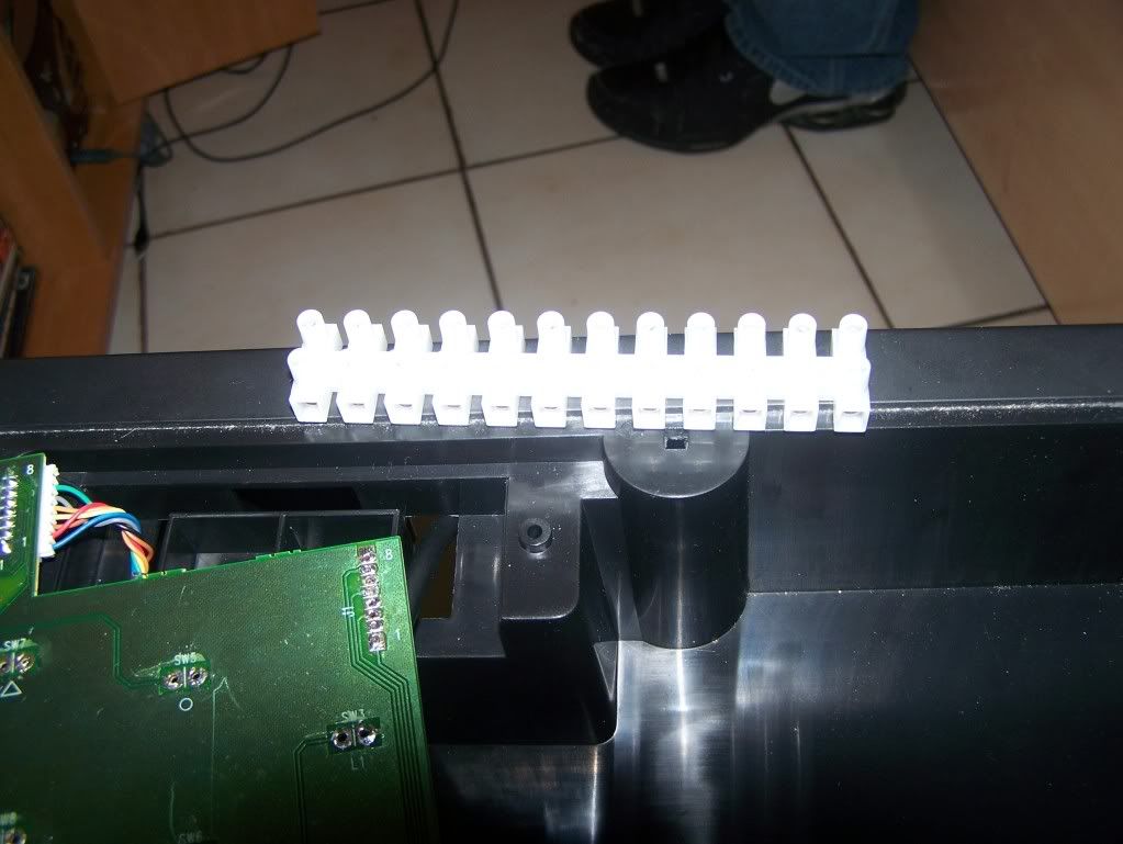
I am confused on an issue about the terminal in the T5 stick…
I have the wiring finished up on the stock Hori PCB that came with the T5 stick (domestic US release) and am waiting on the casing’s new paint job to dry before I reinstall the PCB, connector cable and the new disconnect cables I soldered in last night.
(It was very easy to remove the PCB once I figured out there was vestigial plastic from the T5’s HRAP 1 origins… That plastic probably held turbo buttons for the HRAP 1. Sometimes Hori’s stingy recycling works to your advantage! The plastic could easy be hacksawed off without compromising the base’s strength and allows you to remove the connector cord without damaging the PCB. Honestly, other than wrapping the PCB in plastic {which I didn’t want to chance gettiing dripped on with excess paint}, I figured this was the best way to remove the PCB and PS2 connector cord.)
The only thing I haven’t done is strip some insulation off the stock joystick wiring that I saved (still soldered to the PCB!) as the tutorial instructed before connecting to the terminal.
Anybody have a CLEAR AS MUD diagram of a finished T5 mod that has the wiring in order on both sides of the terminal for the Hori T5 PCB and the Sanwa JLF stick?
Seriously, I’m a bit confused as to what’s ground wire and what’s directional on the T5 wiring. How to do you tell which is which without some kind of marking on the wiring? From what direction (side of the PCB) do you tell which wire is Grey 1, Grey 2, etc., etc. and ground or directional?
Honestly, this is my last big hurdle to get over with this personal project. (The third mod I do is going to be the big one – a dual Saturn/PS2 mod.) I’m waiting on my arcade parts to arrive from Gremlin and probably will print out my custom art for the faceplate tomorrow. In the meantime, other than the parts, I’m just waiting on the casing’s new paint job (navy blue rustoleum brand spray paint) to dry. That’s going to take until at least 6 PM EST Tuesday… I don’t want to chance getting permanent fingerprints in the paint! I had a heck of a time these past two days between spraying and sanding coats to get it up to an acceptable level for myself.
EDIT: Ah! I think I found the answer to my question in a reply by AJtheMishima on 3-18-09. There’s even a nice picture of a Euro terminal just like the one I bought! I will give a go at this later tonight after printing out my artwork and getting a protective clear coat for the paint job on the outer casing…
After a lot of work, I have finally finished modding my T5 stick. The hardest part wasn’t actually the soldering, it was the painting work. If you have any questions ask away.
Inside of the stick.
http://img162.imageshack.us/img162/8946/96243460.th.jpg
Top of the stick.
http://img220.imageshack.us/img220/1958/57772093.th.jpg
Left side where the Home button is.
http://img147.imageshack.us/img147/4533/66613981.th.jpg
Front side where the USB port is.
http://img147.imageshack.us/img147/7899/96203075.th.jpg
^^^^
How did you cover up the existing cable hole?
Bondo?
That’s a nice clean job too. Vinyl dye for paint?
Yes, I used the red one that’s used to prepare cars for a paint job.
For the white color I used Rustoleum specially designed for plastic, and after that Rustoleum Polyurethane to protect. One of each can.
After that, I don’t know how it’s called in English, I believe is called Clay, the one used for giving shine to a car that’s just been painted. Is used it like you would use wax, that gave the controller a glossy finish and protection from fingerprints and scratches.
I’m actually very proud of how it turned out, and being able to do it alone without any help.
Thanks for the info…that’s a kick ass job. I liked how you painted the case, awesome.
nice work, ill have to try that out from my wireless mod next time
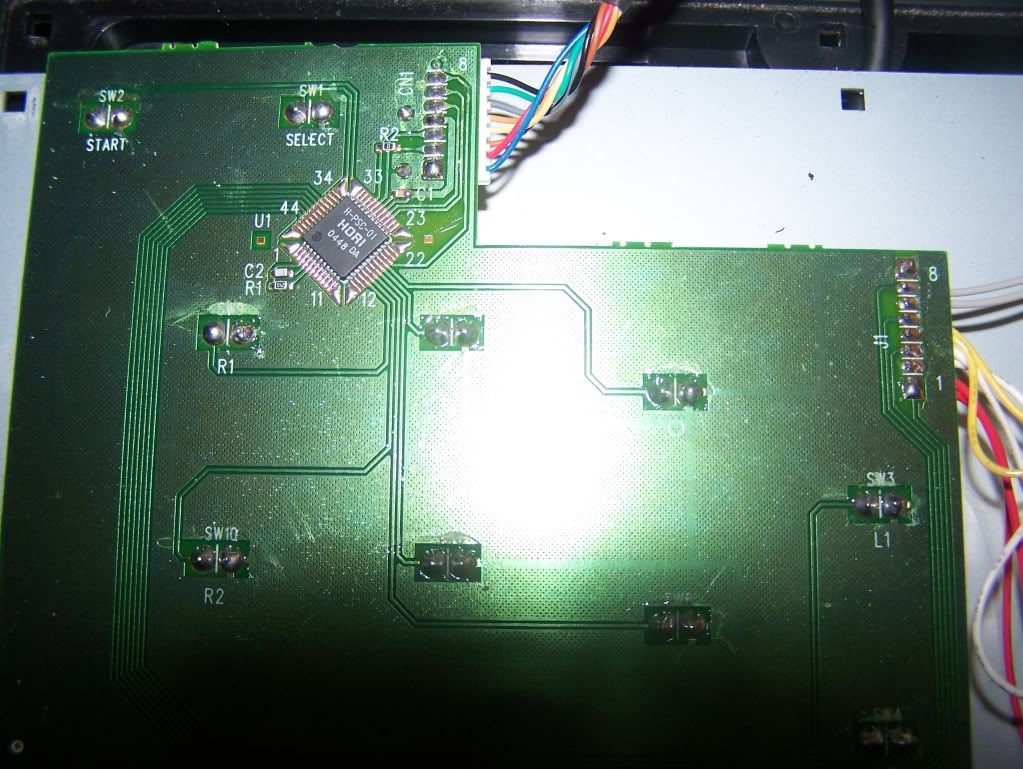
I don’t know if you guys have been doing this, but I just did this today and it worked great.
First, desolder these points. The heat from the solder should help you rip out the hot glue and all of these wires.
http://img13.imageshack.us/img13/8673/desolder.jpg
Then take a small drill bit, I used a 1/16th. Drill through the the first two holes closest to the edge, then start drilling through every-other hole. That should be a total of 5 holes. This will make soldering your JLF harness to the board a lot simpler. If you drill too big or too fast, you could fuck things up, so be careful. Now you can run your wire through the board and solder it on the green side. The one closest to the side is the common ground, the next one is right. The rest of the pin-out is in the first post.
http://kowal.itcom.pl/foto/mod10AT5AS-JP1.jpg
http://kowal.itcom.pl/foto/mod10AT5AS-JP2.jpg
There is an enormous wealth of information here. Thanks to all the experts!
I am currently taking this on as my first mod project with a Sanwa stick, and I have a big noob question:
On a Sanwa JLF, are you REQUIRED to use the Sanwa PCB’s wiring harness, or can you wire straight to the JLF’s microswitches like the original Hori’s was? It seems you should be able to do either/or, but I’m just making sure as I have never done this before. Thanks!
:china:
Well on the JLF it doesnt have the prongs on the switches for you to use quick disconnects, so youll have to solder to the “stubs” of contact points. And i believe youll have to cut the traces on the jlf pcb.
sick mod
Complete Newbie Wants To Do a Dual Mod
Hey guys thanks for the tons of info on this thread. What I want to do is mod my T5 stick and keep the Hori pcb with another pcb for the 360 most likely the madcatz one. Keep in mind I’m a complete newb to this I didn’t even know what a dremel was… My goal now is to keep the stock parts for now mod the 360 pcb in neatly and organized so later I can easily put it a Sanwa stick and buttons with quick disconnects I’m guessing would be the best way. I would prefer to screw the 360 pcb in the case if possible? How would I go about doing this?
Any link Explaining grounding daisy chaining would be greatly appreciated.
I understand I will need a terminal for this(Well to make it more neat and future proof I’m thinking)?
Can I do this under 50 bucks? For materials I don’t have a soldering gun,drill,wire stripper, wire crimper
Last but not least how do I cover the first 2 holes like Vietexan did in his stick? Put the artwork over plugs,no plugs, or specially made real flat plugs? Would prefer the plugs not to show like his stick seen other Hori’s like that too
Only 2 Parts I have
Tekken 5 Hori Stick
Gamestop (Rebranded Madcatz) Controller
Well start project tomorrow and take lots of pictures to help other newbs along the way and keep you guys updated. Well there’s a possibility I fuck my stick up oh well I have to learn somehow.
It’ll be very difficult to do this for under $50 if you don’t have all the tools…
Getting a solderless PCB will cost on the order of at least $30 (closer to $40 with shipping and ALL parts). Any way you slice it, you have to do some work (unless you want to pay someone else with more experience a lot more to do it for you) and having the right tools helps. You don’t have to spend $20 per tool – I was able to find a nice combination wire cutter/stripper for under $6 --, but you can easily spend over $100 in parts and tools to upgrade an existing joystick. Sanwa parts alone – stick plus 8 or 10 buttons depending on the configuration you choose to do – will cost at least $60-$70.
Soldering on the Tekken 5 PCB is a piece of cake compared to control pad PCBs. It’s much, much harder to ruin a T5 PCB than it is a control pad. As inexperienced as I was when I did my first mod I still didn’t manage to ruin the T5 PCB! I’ve since rewired the same T5 PCB with longer wiring (same gauge) and it’s fine. I think the combination of holes and the large contact points on the T5 PCB make it a much easier mod than any control pad PCB. The holes enable you to hold the wiring with pliers while you apply solder to the contact and wiring.
The problem with contacts on control pads is that they’re generally a lot smaller – literally the size of nailheads! However as some people have said, you may only have to HEAT THE WIRING before you apply it to the older point on the control pad PCB. New solder may not be completely necessarily if you liquefy the old solder and let it dry quickly with the new wiring in place.
P.S. – Another option to soldering might be this – http://www.wireglue.us/
I found that URL in another thread about soldering.
I don’t know how good the stuff is or if it even really works, but it might be worth a try for someone.
I do imagine there are technical reasons why most people still solder in addition to cost…
I wanted to add my own questions about the Hori Tekken 5 (US) PCB.
People say it’s a common ground PCB. What does that mean? It’s been years since high school and college physics and frankly I never really understood circuitry all that clearly.
The other thing is that I want do a dual mod and am doing a lot of research on my own (for a PCB a lot of people are not using) and asking questions… I still don’t have an answer to one critical thing about this Hori T5 PCB and was wondering if anybody knows this answer –
Where is the Ground on the power cable connection (of the Hori Tekken 5 PCB) that you have to solder to another PCB? I know the yellow wire is voltage from another post I found a day or two ago.
Believe me, I try to use the “Search Function” on the board but there are so many people posting here and not all the information is in the FAQs or labelled in all the nice diagrams and photos people have been pasting, either…
If its common ground it means you dont have to use the ground that is next to the signal on the pcb for each button. You can use any ground and it will be the same. So knowing that, it means you will be able to use any of the grounds on the tekken pcb to ground it to another pcb.
Okay, gotcha… I think it’s a bit clearer now.
So I could use any of the joystick grounds to finish off a wiring circuit if looped all the buttons (grounds) and terminated at the ground terminal position for the joystick?
Should make it a bit easier for me to figure out a wiring diagram for a dual mod then.
Thanks for the clarification!
Work in progress
Please anyone confirm my diagram of what I think I should do. At least that’s what I understood for the ground on how AJ explain it and thanks for clearing that up. Oh yeah how do I remove analogs sticks try to search but no good answers sorry if been asked before.
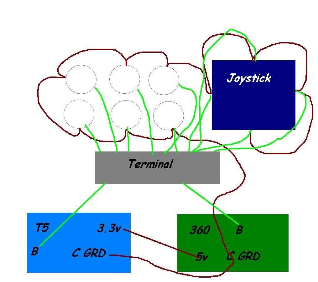
Basic idea
Solder wire from 3.3v T5 to 5v 360
Solder Ground from T5 to 360 then chain to other buttons
Solder all buttons and I should be good to go
So on Terminal technically I should have 12 going in (4 for directions and 6 face buttons and then Start and Select) Please correct if wrong
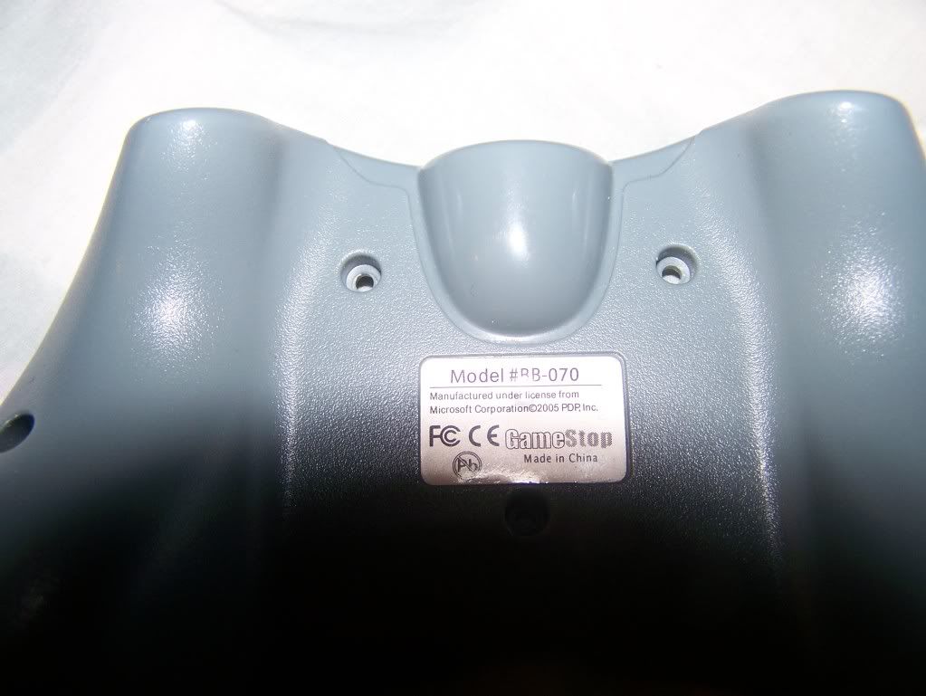
Manage to desolder pcb from Tekken Stick and Joystick found out my current Gamestop Controller is not common ground model #BB-070 so I need to buy a new xbox 360 pcb going for the Madcatz retro tommorow in order to dual mod it.
Pictures for other newbs taking the project to dual mod their Tekken Stick for PS3 and Xbox 360
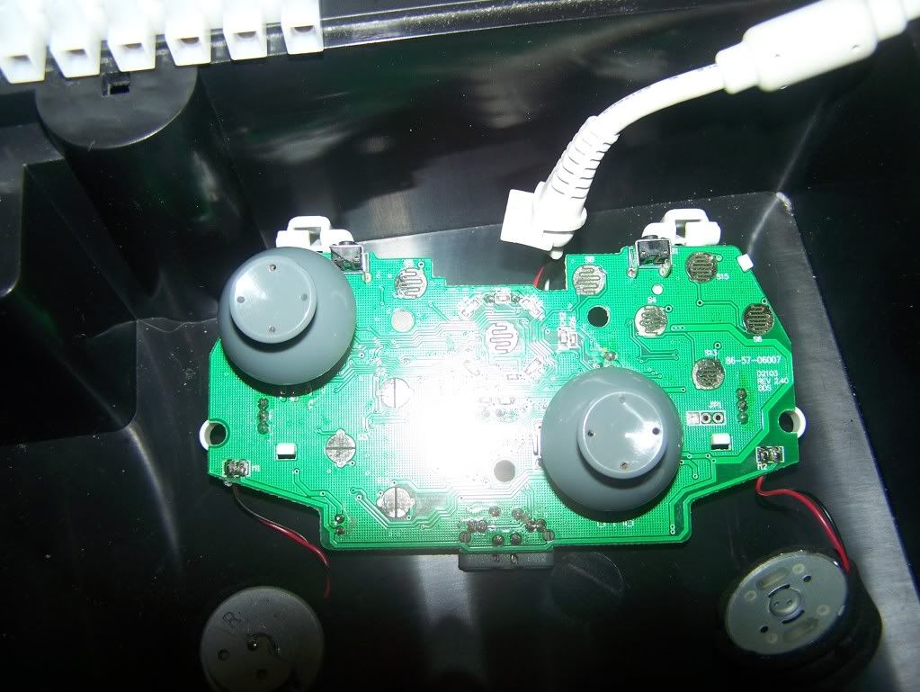
i think the analogs should come off with force, just pull them off. Atleast thats how my 08/09 ones came off.
Yeah, you have everything almost right.
You still have to use one ground from each pcb and run them through the terminal
so 13 ports.
4 directions
8 buttons
1 grounds
Once you do that run your black jlf harness wire to the ground