You’re going to need to use wires. Wires basically extend the connection of those soldering spots. All you have to do is solder on the wires like how the old buttons were soldered on, then either solder the other end of the wires on to the buttons or use quick disconnects.
There is a way of bending the prongs to make them fit like the stock Hori buttons then soldering them back on, but it requires some dremeling of the PCB holes from what I have read from other guides. Maybe Tingboy or another member has pictures of this. Follow this link for the button installation, it doesnt have pics available but it has steps on how to fit the Sanwas’ back on the PCB (ShinJN’s method)
http://himuragames.suddenlaunch3.com/index.cgi?board=techinfo&action=display&num=1109887687
However, I wanted to make mine kind of like the HRAP’s where they have quick disconnects for the buttons, so if I want to swap them out I can without desoldering and resoldering anything. That was the point of all those wires. I dont know how much trouble you want to go through, but you DO have to solder wires to the PCB and crimp the disconnects on the other end. It’s fairly easy, if you desoldered the buttons off the PCB, you certainly can do this.
I will post pics in a bit. I think Tingboy was gonna do a tutorial similar to his HRAP 2 mod tutorial, maybe he has pics of the button installation without use of wires and disconnects, please post them Tingboy. Keep in mind that requires soldering as well.
It just seems like it would be better for me to get some wires at Radio shack.
So basically, if I solder the wire from the button to the PCB, it should be able to read the button just fine, correct? Like if the wire to make the contact with the PCB, it’s all good. Of course, I would have to solder the end of the wire to the board, possibly electric tape it down to make sure it’s good to go.
Yes all you need to do is solder the wires to the pcb and then either solder the wires to the buttons or use quick disconnects. I used .187 quick disconnects and it worked just fine on the buttons.
You will need.
22 awg stranded wire and 0.187" or 0.110" female disconnects.
Desolder and remove PCB
http://img204.imageshack.us/img204/4256/img1291xf8.jpg
Strip wire, twist, and solder to the vacant PCB holes.
http://img405.imageshack.us/img405/9193/img1349ay2.jpg
repeat for all buttons and cut off the excess wire sticking out of the solder.
http://img511.imageshack.us/img511/7743/img1357aj7.jpg
Turn over and you can put a dab of glue on the wires if you want for added strentgh.
http://img511.imageshack.us/img511/997/img1409gl2.jpg
Crimp on your quick disconnects to the other end, connect to the buttons, and presto…your very own HRAP style button set-up. Brilliant! Brilliant! (time to kick back a Guinness)
well your first mistake was owning arcana heart in the first place, hur hur
anyways
solder makes a very strong connection, so its unlikely youll need to electrical tape anything down. solder is like metal glue. you might need electric tape for insulation, or making sure no metal parts touch that arent supposed to.
basically you want to make a metal path between your button and the contact on the pcb. anytime there is a metal path between 2 points electrical signals from one point can travel to the other one.
sorry if this is like really basic electronic stuff and it sounded kinda condescending, thats really not my intention but theres a reason im not a writer
ill post a drawing in a bit which should make stuff a lot clearer
edit: nevermind photos > mouse drawing
I will, once school stops kicking my ass =. Physics + economics isn’t too fun lol
Wow, thanks for the info and pics, but…
Wondering how exactly did you get that?
I mean, I don’t think I need to do something like that if I’m plugging in the cords from the other side of the board, right?
And I suppose gluing them down would be a better idea than tape, huh?
hold up ill draw a picture for you
the glue/tape is optional, solder is pretty damn strong
EDIT: here you go
http://img367.imageshack.us/img367/976/wiringjc9.th.jpghttp://img367.imageshack.us/images/thpix.gif
Im trying to swap the stock stick for JLF…my JLF has a S plate mount so it doesnt fit the stock mount…how do i make it fit? am i suppose to take off the stock mount on the control panel? if thats the case i dont have the tool to take it off.
Take off the mounting plate from the JLF, then drill 4 holes through the gate. After drilling the holes, use the 4 original screws from the Hori stick you just took out and insert it into the holes you just made. I posted a picture of my mounted JLF. It’ll show you where to drill.
I’m going to see if I could shoot chad an email about getting JLFs without the mounting plate. All of the mods that I do I end up stripping the 4 small screws that hold the JLF to the mounting plate. I don’t know why they insist on using locktite on the screws!!! Plus the noise it makes when I’m tapping the screws out is horrendous lol.
I see, hmmmmmm…
Thanks for the little drawing :tup:
this has become a VERY good tutorial for the t5 modd now… quesiton…what kind of glue do you guys use to glue together your artwork with the metal plate?
just finished mine:
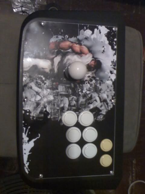
Very nice, nasirjones. Can you explain what materials you used to produce that artwork, where you got it printed and how did you stick it on the plate? I tried different ways but none have produced very good results for me.
thanks
what is the best way to remove or clean excess solder from the PCB?
the solder sucker i have doesn’t work well
I use paintshop pro to edit the wallpaper to the right size then print it out on a legal size paper and went to Office Depot to get it laminated (ask for .5 mm lamination)…I didnt use anything to make it stick…the screws are good enough to hold it down.
try a desoldering braid aka solder wick and if that doesn’t work then it’s time to step up to the big time and get a solder sucker like mine.  :smokin:
where did you get that SS?
also (a never ending question) what size do peepz print the artwork to put on the panel?