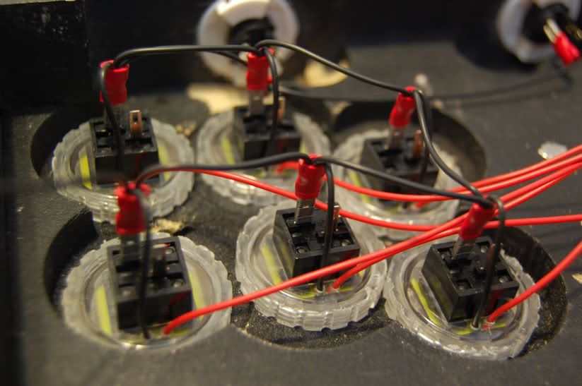
The common line is soldered to the right half of the Down button from the Dpad, and I just have it daisy chained across all the buttons. I forget who’s method I copied, but for the KNserts I just connected the ground wires to the daisy chain. Sorta like this, only not NEARLY as clean lol.
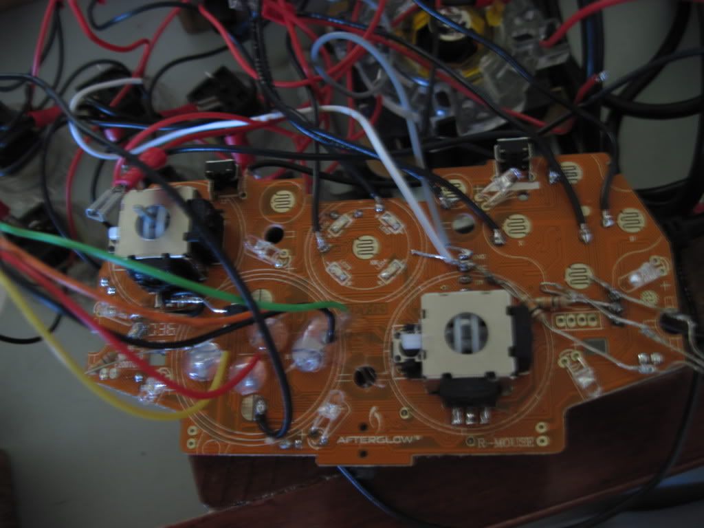
Well I got a picture of the front of the PCB but I don’t know if that helps, everything’s such a mess that I feel like I’d have to redo my wiring so you can see what’s going on -_-
Whoa. May need to go the other way around on this. Use a meter to check for continuity from the FGW ground point to the ground point the USB wire is connected (where the grey wire is soldered in the pic above).
Then plug it in, and test voltage on the FGW VCC point. Let’s verify the LED controller is getting power at least. For the time being, keep all wires off of the *_IN points on the LED controller.
Ok, I’m really bad at this
I’m not sure exactly what to do with my multimeter. It has DCV, ACV, DCA, and OHM settings. I set it to 20V in DCV, but I don’t know if that’s right. I tried testing ground to ground and VCC to VCC but I didn’t get any readings on the meter at all. I don’t know what I’m doing lol :oops:
Well I definitely saw something I didn’t notice just a bit ago. It’s very possible I put the middle black part of the FGW on backwards. I just saw that the notches don’t match the white line on the board. I’m gonna feel really dumb if that’s the problem.
Hahaha I’m sooooo dumb! Any tips for desoldering something with so many tiny pins? I can never suck up all of the solder from those points.
I’m glad the mystery has been solved. Lesson well learned, I’ll be more observant in the future -_-
Thank you so much for all the help jdm, Nerrage and Toodles! <3 <3 <3
Okie doke. I tried using it earlier but I’m really not sure how to use it right. There’s different settings and I’ve messed around with them but I can’t really seem to get a reading on it.
Ok so I think I might have gotten something, I set my multimeter to the OHM setting and tested ground to ground. When I set it to OHM, the screen read as 0L, which according to the instructions means that it’s reading a value too high for it’s threshold. So once I put ground to ground, it read as 0. So does that mean there’s continuity?
Oh and then I tried testing VCC to VCC with different settings on the multimeter to see if anything would work and I accidentally touched one probe between VCC and Ground and fried my PCB. Sooo I’ll be switching that out tonight :looney:
At a guess, you had it set to measure current, and using those probes on those spots blew the current fuse in order to protect the electronics. Please dont take this the wrong way, but dont mess with the current (‘amps’) setting until you know what you’re doing. Resistance (ohms, greek omega symbol) and voltage (V symbol) are all you need and should use. Check the book that came with the meter to see if you can easily replace the fuse.