Help! Stick freaking out after FGWidget mod

So after wiring up my FGWidget and plugging in my stick, I found that none of the buttons besides start, back, guide, and A worked correctly. I managed to get into MVC training mode to see what was going on with the inputs, and I’m getting a near continuous input for B. In game, A, X, RB, LB, LT, start, back, and guide all worked but with almost every button I push there’s another input for B. Oh and there’s no problem with the joystick. The LEDs are on a constant dim setting, and every once in a while there’ll be a bright flash on my Y button when I try pushing another button.

I made sure to double check my wiring and I put everything in the right place, I didn’t see any solder bridges or anything touching that shouldn’t be touching, I’m really not sure what to do here. Unfortunately I wired everything up in such a way that I can’t really take clear pictures of what I did. Does anyone have any idea what could be wrong? If I need to I can take the time to clear up the insides so I can try to get a picture. Any help would be appreciated!

What Arcade Stick you used?

It’s one I built, I’m using an Xbox afterglow PCB if that makes any difference. Everything worked fine before I wired up the FGWidget.

Is Afterglow a Common Ground PCB?

Yeah it’s common ground.

Just to cover what I did with the wiring:
Ground to ground from the PCB to Widget, VCC to VCC, power from the KNserts to the “_OUT” spots, and I have a wire from the signal lines of my buttons going to the “_IN” spots, and ground from the KNserts are attached to the ground daisy chain.

Which KNserts are you using?
v1.2 or v1.4?

v1.2 I believe

If you removed the FGWidget LED Controller, will your Arcade Stick work correctly?

I just tested it and yeah everything works perfectly fine without the FGWidget attached.

Bumping my own thread because I’m desperate for help :frowning:

I think the afterglow is common high? It would be wired like common ground, but everything would be upside-down, I think.

But that’s just my guess. I’ll have a PCB from one eventually to test, because some guy wants me to Dual Mod his MC Cthulhu with one.

Hm, sounds weird lol. What exactly would be upside down?

But here’s the other thing, before I used the afterglow, I was using a madcatz fightpad PCB. I had the same problems unresponsive buttons and extra inputs, so I thought I had just done something whacky to the PCB since I shortened the USB cable to use a neutrik adapter. So I switched that out for the afterglow controller this time leaving the USB alone and I got the same exact problems T_T

Darksakul should know; I think he used one for a twinstick job.
Svenuser, you comfy with a multimeter? Because some voltage measurements would sure help.
If not, then remove the wires from the *_IN points. Leave the Knserts wired up, but dont connect the signal lines to the FGW LED controller. Let us know if you see the normal light patterns on the KNserts; you may need to connect JAB_IN, STR_IN, and FIE_IN to GND with some wire to force a reset and they should light right up.

I’ve never really understood how to use a multimeter, but if necessary I could pick one up tomorrow and try to check things out! Would a cheaper one from radio shack do the job?

Edit: Ok I’ll try that out with the wiring and let you know what happens once I finish.

Cheaper one is typically analog. Analog are a bit harder to read. Radioshack had a nice digital one, but they’re like $30.

Any time you test, if you have a good estimate of the readings, always set the multimeter to the lowest threshold that contains the expected readings. For example, everything on USB is a 5V max. My multimeter has thresholds of 1V, 4V, 40V, 200V, etc. Since I expect everything to be in 5V ranges, I’ll use the 40V setting of my meter. Some digital ones can set it for you, but I never like when it cycles between the 4V and reports three decimals, then back to 40V and reporting only two decimals. Same for resistance and current.

For voltage measurement, have the board powered. Place the black probe in the terminal of the multimeter labeled “COM,” and the red one in red terminal labeled “fused,” if your multimeter has three terminals. the unfused is only used when measuring higher amounts of current.

Place the black terminal on a known lower voltage, typically ground. Since measuring voltage is measuring a difference, you don’t always have to measure from ground. Then place the red terminal on the higher voltage. The multimeter will report the difference between the black terminal and the red terminal. In all of these tests to find a specific voltage of a specific point, you’ll want the black probe to be on ground, as it is 0 volts, so any difference in voltage will be the exact voltage of that terminal.

For resistance measurement or checking continuity, leave the PCB unpowered. Color does not matter. Probes are same as voltage. Probe color does not matter. Point the probes to the points you want to measure the resistance across. A special case of this is testing continuity. Continuity tests whether or not these two points are connected. If your multimeter has a beeping continuity tester (most digital ones do), set it to that mode. If it beeps, the points are directly connected. No beep means no connected. If yours does not have this feature, then you can turn it to resistance, any threshold will do. It will report at a high level. If you touch the two points you are trying to test, and it drops down to almost 0 resitance, then you have continuity.

To measure current, you will need to break the circuit. You will also use the “unfused” terminal for the red probe if you expect to have measures above the max rating of the fused section (varies from meter to meter. Mine is 400 mA max, which will cover most USB applications). Break the circuit between the two points you are looking to test. Place the red probe where the current is coming from, and the black probe to where the current will be going to. Or maybe I have that backwards. If your meter goes down, it was backwards. Mine just reports a negative reading, but then I remember which way it should go.

Thanks so much for the explanation! I’ve always kinda been in the dark about using a multimeter lol.

Ok so I took out the wires from the IN points and there was no response from the KNserts and all the buttons worked just fine. Btw I’m afraid that with too much soldering and desoldering, I might accidentally remove one of the metal rings from the FGW. If that happens, am I kinda screwed?

So on the chance that I had just crossed some wires or something the first time, I rewired everything on the FGW and I had similar problems as before. This time there was no constant input of any button but rather just multiple inputs with every button push except for start, back, and guide. If someone could tell me what exactly to test for with the multimeter I’ll pick one up and check it all out tomorrow and post what I find. Thanks so much for the help so far, guys!

It is not Turbo?
I don’t know if Afterglow has Turbo.

No there’s no turbo function on the afterglow controller, something’s just freaking out :frowning:

Weirdness. What needs to be tested is voltage; the voltage on the common wire that goes to all of your pushbuttons, and the voltage on at least one of the signal lines when that button/direction is not pressed, and the voltage on that signal line when the button/direction is pressed. Do those with the signal lines NOT connected to the FGW LED controller.
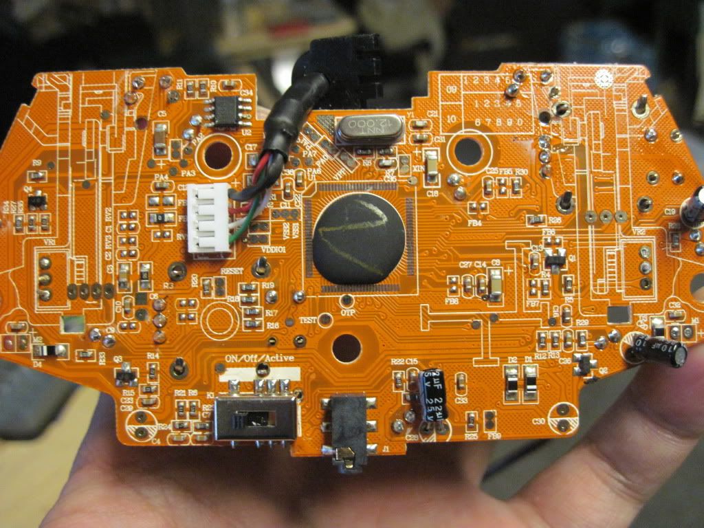
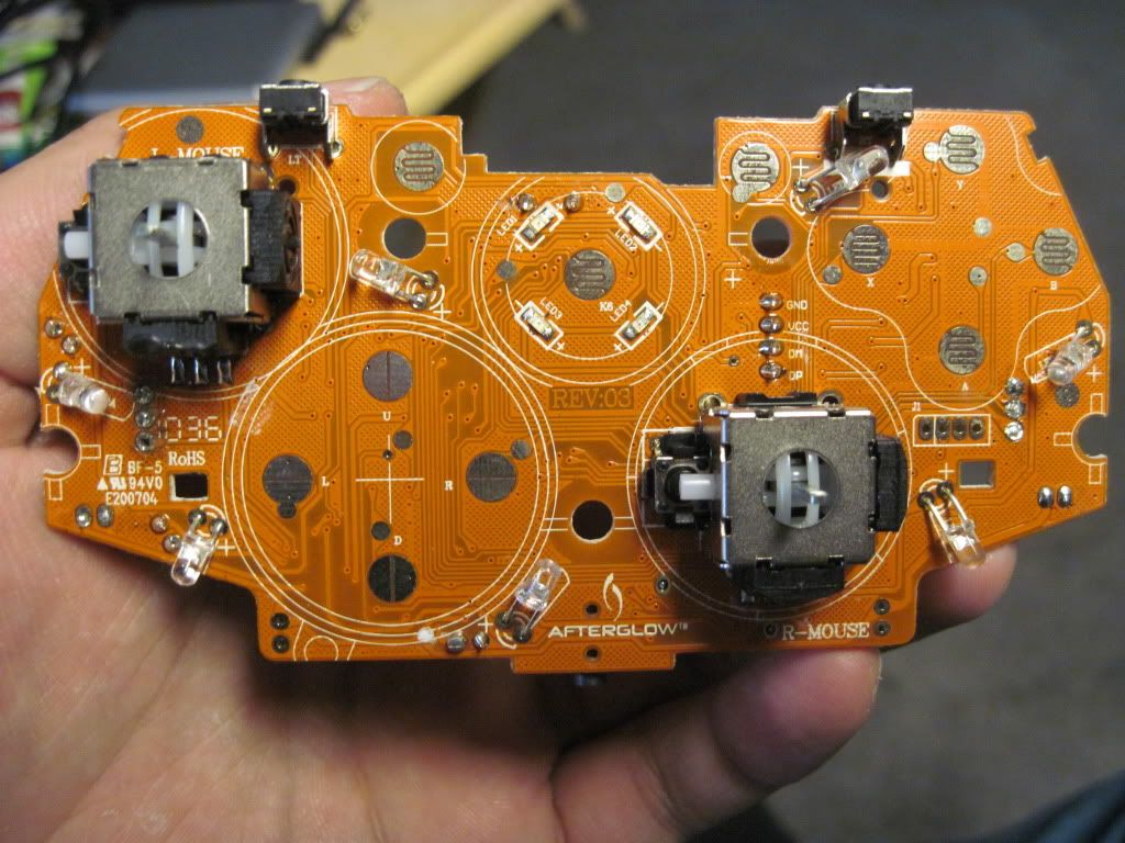
It would also be helpful to get some close up good macro (flower mode) pictures of the afterglow PCB you’re using.

Edit: found the pictures you posted previously of it:

Sure as hell looks common ground to me, at least for the face buttons. Can you please point out how you have the common lines wired up on the stick, and where they are soldered to on the pad?