done… thank you…
Couple questions if i may.
- Does this 7400 chip require pull-up resistors? http://lib.chipdip.ru/058/DOC000058151.pdf
- If yes, where should i solder them?
- I think those HC versions will, just like those HCTs BlindWithOneArm had did.
- One end on power, other end on the direction. Repeat for every direction.
The end connecting to pin 14 is correct, but the other end needs to go to the two input lines, not the outputs.
Ok, thank you!
Made 2 videos, check em out:
Sorry for bad lighting/low audio
Thanks for providing the nice diagram DanAdamKOF
http://img267.imageshack.us/img267/8763/hitbox2superwire.jpg

instead of A input directly to 5 and B input directly to 9,
shouldn’t it be 5 -10 and 9 - 4?
as this current drawing.
A-in B-in A-out B-out
0 0 1 1 Both outputs on
1 0 1 0 A on, B off
0 1 0 1 A off, B on
1 1 0 0 Both outputs off
new drawing should be

Original in the first post is correct. I do not understand why you would want both outputs ‘pressed/active’ when both inputs are ‘unpressed/inactive’
but in the original, thats what you get?
0 in on A = 0 on 5, 13, 12,
0 in on B = 0 on 1, 2, 9
0 on 13 & 12 = 1 on 10
0 on 1 & 2 = 1 on 4
1 on 10 & 0 on 9 = 1 on 8 (A output is on)
1 on 4 & 0 on 5 = 1 on 6 (B output is on)
so have i read the original wrong?
on mine on no input you would have no output.
Your drawing is this:
FA = ~(~A & ~B) = (~~A ^ ~~B) = (A^B)
FB = ~(~A & ~B) = (~~A ^ ~~B) = (A^B)
A B FA FB
0 0 0 0
0 1 1 1
1 0 1 1
1 1 1 1
So the only time either output would be activate, BOTH outputs would be activated, and that’s only when both inputs are pressed. The only line of that truth table that is desirable is the last line. The other three are wrong. Please use the drawing in the original post.
The original post drawing is this:
FA= ~(~A & B) = (~~A ^ ~B) = (A ^ ~B)
FB=~(~B & A) = (~~B ^ ~A) = (B ^ ~A)
A B FA FB
0 0 1 1
0 1 0 1
1 0 1 0
1 1 1 1
That is the correct truth table. Please remember, on a common ground PCB, active lines are LOW voltage. High voltage is an unpressed/unactivated line.
yup i messed up on mine lmao, but still the original has both outputs on when both inputs are off?
They’re not “on” they’re pulled high.
Hey, wanted to clarify wiring one of these up - I would totally just buy the kit, but I need this mod done ASAP for a tournament on Saturday, and I’m not sure it would ship in time.
I do have a Fry’s in town, though, and they have these chips:
(datasheet that I assume corresponds:
http://www.americanmicrosemi.com/information/spec/?ss_pn=NTE7426
Will I need pull-up resistors? (To be clear, what value would be best?) Would it be okay to just wire resistors from pin 14 (vcc) directly to pin 5 and pin 9 in this diagram?

If anyone at has the answer for me, help me out - …otherwise, I’m just gonna go for it and hope it works, lol. I guess the worst that will happen is I waste a few bucks, and my buddy won’t be able to enter the tourney.
Whether or not you’ll need them depends on both the chip and the controller PCB, so I cant give any solid answer. If I were you, I’d expect to use them, since the setup will always work with unneeded resistors present but wont if needed resistors arent present. Use something in the range of 4k-20k ohms. 4.7k and 10k are very common and easy to locate. Yes, you can put them directly to the pin numbers you mentioned.
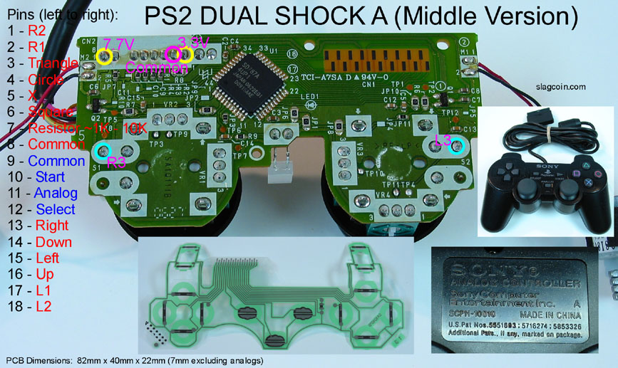
That filter work with dualshock 2 PCB that has common ground for most buttons (although with some resistor arrangement) and additional ground for start-select-analog. What can be the problem?

edit: multimeter reads only around 0.5v on buttons when they are not pressed. When i solder on filter it sends around 0.2v whether they are pressed or not. Chip is powered by 3.3v from PCB.
hi i tried using it on my hitbox equipped with ps3 chtulhu, i use it on pc
initially i did only the l+r=n mod, but then i realized that i needed the up+down=up too, so i added it on my board
i used the two diagrams in op, l+r works ok but up+down has some problems, down isn’t pressed ever, i’ll press it but it didn’t work or works for a blink of an eye (i tested on joystick panel of windows)
i tought it could be a 7400 faulted, so i swapped chips but the same defect appear (i mounted them on sockets)
could it be the power source?
i used the chtulhu to power the two chips wired as this image

did someone encountered the same problem? or has some suggestion?
thanks
Are you using a DIY “Hit Box” or the official Hit Box?