How about using two 7400s, one for L+R=N and the other for U+D=U ?
Is that feasible?
I think OP scheme of L+R=N has an error - if A input gives 0 (button pressed), filtered output A will be 1 (button not pressed), and filtered input B will be 0, and vice versa. If both inputs are 0 - both outputs are 1. So filtered outputs should be flipped.
Agree with RoBoBOBR. In OP Filtered A = /(A & /B) == /A | B
A B Filt. A
0 0   1
0 1   1
1 0   0
1 1   1
Up + Down schematic is correct though.
Also, it’s probably a good idea to add pull-up resistors. If you’re using a CMOS chip (like the HC variant) you may well need them.
You guys are right! New diagram coming up. This is why I like Tech Talk.
edit: It’s up, refresh if you see the old version. Thanks a ton, RoboBOBR and Icy Black Deep 
So i tried this using 2 chips by itself and then again using a breadboard, I only get Up. I verified voltage is 5V on both boards.It just seems like the chips aren’t doing the job, as Up is the only one that is bypassed.
These are the chips I ordered:http://search.digikey.com/us/en/products/SN7400N/296-14641-5-ND/555975
Just curious if there’s anything I should know other than to follow the diagram, such as daisy chaining the chips together for power/ground/etc.
If possibly, DanAdamKOF do you have pics of your breadboard and/or installation into a hitbox?
Well yes you for sure give power and ground to each chip.
I don’t have pics, but here’s some visual aids, excuse the MSPaint. This only shows how I wired each 7400, I’m assuming you know how to padhack and all that otherwise.
Didn’t say these would be pretty…
Oh, the big grey dots are blobs of solder joining the two pins together, that’s how I did it.
A+B = NEUTRAL (where A is LEFT and B is RIGHT in this diagram)
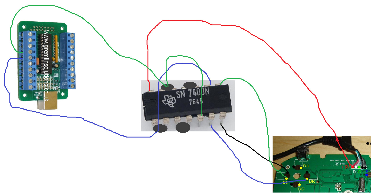
UP+DOWN = UP
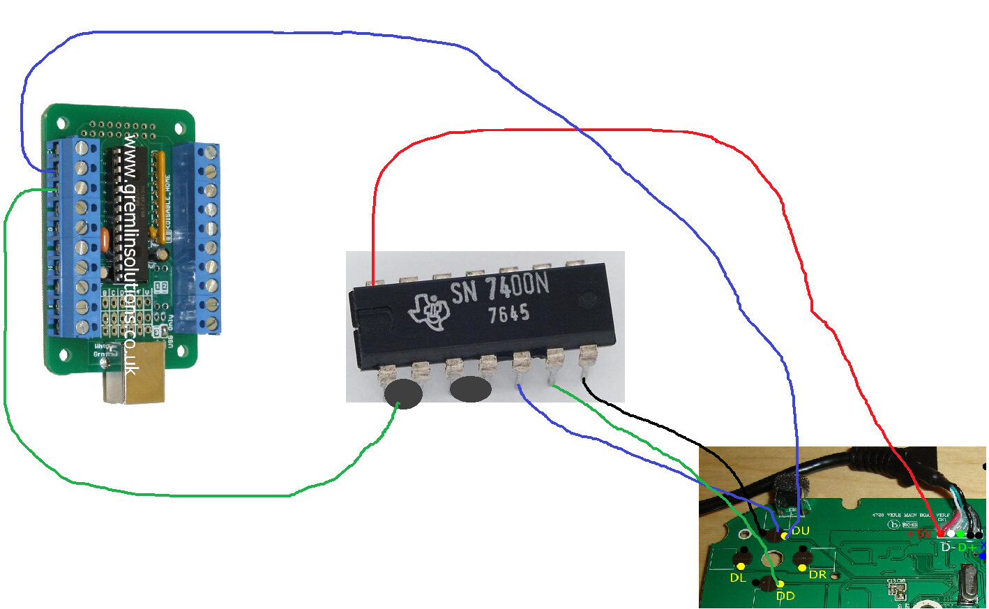
I scribbled these out in like 3 min each so it’s possible I messed up somewhere, but it looks right to me.
Ok I did that but the exact opposite. Aren’t the legs towards the end (filtered outputs) supposed to go to the cthulhu and not the fightpad?
The filtered outputs go to the PCB you want to give SOCD filtering to. The HitBox’s Cthulhu has SOCD filtering so you only need to put the outputs into the 360 (or whatever) PCB which doesn’t filter SOCD.
Hahahaha ok I see where the problem lies, thanks! I’ll keep you all updated!
Ok yeah I’m an idiot. Thanks a lot for the diagrams! I’ll be making some for future use/sale, I’ll keep you guys informed!
here’s the before shots of the board I used, with the inputs/outputs reversed:

I fixed that, and then got bored and made this:


My friend came over and had some GPS wiring, so I had just enough to make one of these haha.
Can’t see the pictures =(
shows up fine for me but here’s links:
Oh. For some reason tinypic will never load for me. I don’t know why. Tried to turn off adblock but… still not working. Nvm!
Anyone know where to find and purchase an 7400 chip. I got a potential client who want SOCD.
I got the Dis from the thread, but recommendations where to get the chip would be helpful.
frys electronics… if there is one near you…
There’s a digikey link in the OP, I guess I’ll edit it later to make it more obvious.
Going from memory here, but I looked at Fry’s before and they didn’t seem to have the proper 7400, I think the closest thing they had was a 74XX series chip with 4 NANDs like a 7400, but it required pullup resistors since it was a variable voltage chip. That will make things more complicated to wire up.
so for those that DID get the 74HTC00 like I did… what pull up resistors am I looking to get to help this along… or is it a lost cause… yea… pretty pissed that this was missed by me when I went to purchase…
Any can work fine. Just grab 4.7k-10k or whatever you have handy. You dont want to use really low resistors like youd use for LEDs, you need higher value ones. Nothing lower than 1k, and just about anything from 4k-1M should do. Lower value means more wasted current, higher value means longer time for the voltage to rise on button release. That’s the trade off. the 5k-10k range works well as a good compromise.