GUIDE: Preventing SOCD on any common-ground PCB by using 7400 chips

It looks like people have been confused, misinformed, or ignorant about preventing SOCD (Simultaneous Opposite Cardinal Directions, such as inputting Left and Right at the same time) on All-Button Controllers (ABCs). I’ve seen posts on SRK such as “If you dual-mod a HitBox, the other system won’t have SOCD prevention” and “I converted my stick to an ABC, but I wish I had SOCD prevention on it.” I created this thread to show everyone that it’s possible to add SOCD prevention to any common ground PCB, and how to do it. I am by no means a Tech Talk guru, so if you see something wrong or have something to add, please speak up!

SRK member Rufus figured out in the “The “Stickless Arcade Stick” Thread” thread that you can use 7400 chips in order to prevent SOCD. 7400 chips are microchips with 4 NAND logic circuits inside of them, and by wiring them up a certain way, you can get them to disallow two inputs on an axis from reaching the PCB.

You will need one 7400 chip per axis. For easiest soldering, you would want to buy 7400 chips meant for through-hole soldering, such as these.

The circuit below will cancel both inputs on an axis to Neutral.

The circuit below will cancel Up + Down to Up. This is how the HitBox handles Up + Down. Some prefer this over canceling to Neutral, because it makes Super-Jumps come out quicker.

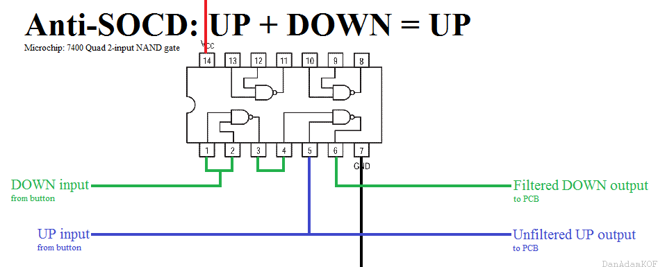
You install these circuits between the button’s input wire (not the ground wire) and the PCB. The button’s input wire goes into the chip, and the filtered output (which has SOCD prevention) comes out of the chip and goes into the PCB. You also need to provide power to the 7400 chips, so connect Pin 14 (Voltage) to Voltage on the PCB, and connect Pin 7 (Ground) to Ground on the PCB.

Some notes on these circuits:
(Optional) For cleaner wiring, you can use a blob of solder to join two adjacent legs instead of using wire.
Each 7400 has a maximum power draw of 22mA according to the datasheet.
If you’re worried about input lag, the circuits within the 7400 chips are comprised of discrete analog electronic components with no microprocessor. Therefore, the amount of lag in these circuits is technically a few (<25) nanoseconds, but a 60fps frame is 16666667 nanoseconds… in other words, they don’t lag. Check the datasheet if you doubt me.

Some notes on installations (these assume you have built the circuits already):
If you are converting a stick to an ABC, or building your own ABC, or installing these into an ABC without SOCD prevention, and want to prevent SOCD on it, you can install these circuits by connecting a piece of wire to your direction button (the input side and not the ground side), soldering the other end of that wire to the appropriate Input on the 7400 circuit, soldering another wire to the corresponding Output of the 7400 circuit, and connecting the end of that Output wire to the direction on the PCB. If you’re installing these into to an ABC without SOCD prevention, disconnect the wires that go directly from your button to your PCB before installing these circuits.

If you are dual-modding a HitBox and want to prevent SOCD on your other PCB, you can install these circuits by connecting a piece of wire to a direction’s screw terminal on the HitBox Cthulhu+ PCB, soldering the end of that wire to the appropriate Input on the 7400 circuit, soldering another wire to the corresponding Output of the 7400 circuit, and connecting the end of that Output wire to the direction on the other PCB. edit: I posted an ugly visual aid for using 7400s in a HitBox dual-mod later on in this thread, click here if you want to see it.

edit 01/29/21: Rehosted images on Imgur, because fuck Photobucket.

Hmm…
I was always under the impression from Rufus’ diagram that the L+R inputs were linked to the ground wire because of the switch in his original diagram…
Maybe that was why it wasn’t working for me…

Also be noted that normal 7400 chips only work for the rated voltage expected from a USB line, so if you are using this on a PS2 or non-usb based console which requires less voltage than 5v, you may run into problems.

I had tried it using this version of the chip but I was unsuccessful but then again how I wired it may have been incorrect which led to my frustration.
http://www.chipcatalog.com/TI/SN74HC00N.htm

chip is rated to work with voltages from 2v-6v

Going to try this again with the updated diagram when I have time and update with results if this does work for PS2 and such.

1/60 of a second is 0,166666 second, not 16,666 nanoseconds
I only briefly read your message but no doubt it’s very interesting. However, All-button controllers didn’t really catch-up in my area so I don’t know if I’ll ever need this piece of info. Good game though

Sorry, check your math.
edit: Is this some confusion over how some countries use , as the decimal place and some use . ? I just clarified that part in the OP.

0,1666… seconds is 1/6 of a second.
1/60 of a second is 0,016666… seconds or 16.666.666,6… nano seconds.

I guess I should have indicated PCB/ground. It occurs to me that all of these circuits might also need pull-ups, or does the 7400 do that too?

They don’t need pullup resistors. There’s certain 74XX series chips that need it but these have internal pullups due to assuming a +5V voltage, something like that.

Those chips require 5v, i’m planning to eliminate SOCD on a DualShock 2 PCB, which has 3.3v and 7.7v pins. What should i do? =)

Could we take the 7.7v and either divide or regulate to 5v?

Yes, I thought the comma was there for the decimal place like you said and I definitely need to check my math (would you believe I’m a math teacher ??? cough)

EDIT: FreezerB: If you’re using a voltage divider from the 7.7V, there’s no guarantee you can draw enough power from there (I can’t find the specs for the PSX game ports - maybe you’ll have more luck in this)

Posted in the Stickless Arcade Stick thread. I know it’s complete overkill, but it seems like enough people are considering stickless controllers, and a subset of those people aren’t up to the challenge of making a cleaning circuit. More, it would be easy enough for me to make it much smaller than most people are capable of making it via a proper PCB and surface-mount parts; would people be interested in a small, “just works” solution? BatchPCB would let me do a relatively small run while keeping cost way down.

check my post on the second post, i’m not sure it’ll work 100% but it is rated to run between 2 and 7 volts so i don’t see how it won’t work. i just wired it up incorrectly last time and haven’t had any time to try again

Getting a bit nonstandard, but if you tied 3.3V and 7.7V together you’d get 4.4V, which could be close enough to 5V to make the chip happy? Just a thought.

Does it use the 3.3V or the 7.7V for the “signal” or both? I was looking at a Quad NAND gate other than a 7400 and the data sheet stated that the voltage accepted was up to 20V but the input voltages accepted would be VCC voltage ±0.5V. So mixing the 3.3V and the 7.7V would not work even though the IC technically can operate at 3.3V or 7.7V.

IIRC the 7.7 V line is for the vibration motors.

i was just about to say that

you’re supposed to use the 3.3v for the actual pcb and the 7.7 line is for your rumble
that’s why that pin doesn’t exist on the digital pads in terms of being on the pcb

Hmm, I wonder if it would be possible to use these to make a nice, solderless, SOCD filter board.

We’re discussing this in the other thread :slight_smile:

Ok, I’m supposed to use 3.3v, but 7400 needs 5v. How can I increase voltage?

like i said in post 2
use this chip
also a 7400

http://www.chipcatalog.com/TI/SN74HC00N.htm

Oh, sorry, i’m blind )