Fixing PS3 USB Paradise Cthulhu and Dreamcast via J-45 working, Other RJ45s not

The cheapest and quickest thing once can do is the stuff one can do one’s self, as opposed to sending and paying for outside help.

Stan ( my hired joystick maker) is asking for help. Based on a whole slew of advice, (mixed with snarkiness) these are important pieces i think Stan should do in order.

Based on that diagnosis, thee are 4 possible things that are wrong, they are (in the easiest and cheapest order both part and labor wise):

  1. One or more of the Rj45 M-M cables or F-F cables are either broken or not a straight hookup

Way to fix this. If Stan has and knows how to use a mulitmeter, he should use it if he’s jutt doing it this once for me. If we wants to build for my friends adn others maybe, to save time he may want to invest in this:

I know a multimeter is more versatile and cheaper, but if one is frequently dealing with RJ45s, like fight stick makers, if you have to take off the heads of the RJ45 cords to expose wire, and go a multimeter test, and possibly put it back on, this would save labor and time.

Other RJ45 testers are more expensive testing for standards that make it work with a network (twists, etc.). All stick makers need it for is to make sure all paths light up ad go 1->1, 2->2, etc. So that cheap model should work.

Just go to the store and replace failed M-M ad F-F cables. Add one extra one or step 2

  1. Either the RJ45 wire soldered in the RJ45 solder point on the Cthulhu is either,
    2a. a using a non-straight or broken RJ45 cable soldered in originally, or
    2b. a mixed up soldering . (He said he followed colors instead of geographical pin arrangement position. I told him not to do that and he insisted on it anyway.)

I think testing it is more trouble than just replacing it

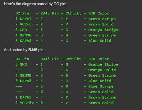
The Cthulhu has a soldering arrangement of this in a row : G A B C D E F V

Since most people on SRK rely on physical positioning of the cable and not the color code so write the color down of a corresponding position trough observation so they know what color on their particular pieces match up with what what position on the soldering.

So if the eject latch is on the top and have 2 rows of 4, and it doesn’t matter which end you use, then you have:

  • L
    1 2 3 4
    5 6 7 8

Should I assume the order is
G->1
A->2
B->3
C->4
D->5
E->6
F->7
V->8

?

  1. The next step is the CRJ45-> Console adapters may be wrong. I dealt with a guy on ebay who pairs these things before by buying 4 adapters from him and having only 1 of them working, the Dreamcast one. I’ll write him and see if’ he’l repair his or others for free for his to a nominal fee or ones not bought from him.

Does anyone think Stan can fix it himself if walked through by this guy? He thinks he can.

  1. Finally if this doesn’t work, I guess I’m going to have to go back to Pardise to fix the Cthluhu.

This is going to be easier said than done for me.
Well I write back to and ebay seller of refurbished RJ45 adapters. And he said to reinstall the RJ45 connected to the Cthulhu.

Do I have the t2 main points right?

  1. The most important thing is the the holes are organize in an RJ45 positional standard for every thing to correspnd. If you hook ONE END by color, you ruin the 1->1, 2->2, etc., correspondence. Becaiuse it’s just a set of 8 organized cables, like a DB9 or something like that.

  2. the hookup is, assuiming this is the hookup:

1 2 3 4
5 6 7 8

and this is the correspondence:

G->1
A->2
B->3
C->4
D->5
E->6
F->7
V->8

Would the ejector clip be above the 1234 row or below the 5678 row? That’s the only thing that’s ambiguous.

And Stan STILL insists on hooking up by color. Everyone is telling me, and I’m trying to tell Stan: F*** THE COLORS. GO IN POSITIONAL ORDER. I literally told him that last night and he STILL doesn’t get it.

And he says he’s good at following directions from a buyer.

Just take the head off, and the first thing you do is observe, and write the color of the cables that correspond to the 8 positions. If Stan must use the colors for easy reference, don’t get them form a book a standard, go by what you see. Then he can hook up by colors to his heart’s content. AND THROW THAT AWAY once you’re done, because you can’t guarantee the next one will have the exact same scheme.

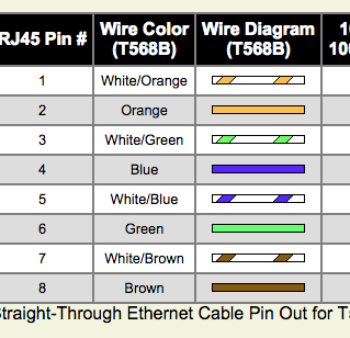
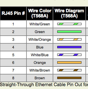
Here’s a website that explains why there’s 2 color conventions and why a joystick maker can’t go off colors for RJ45s.

Both the pins AND pairing matter if you’re dealing with a wired Ethernet network in any way. network connections has corresponding twisting pairs. The $100+ RJ45s can tell you which of the 2 standards, T568A or T568B, the cord is, and if it’s up to more detailed specs.

The cheap <$10 RJ45 pin tester only tests wheether a signal passes throught and which corredsponding pins it comes from and goes to.

And sorry anbout my ignorance about a 2 rows of 4 arrangement… it’s a straight across arrangement.

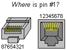
So assuming this is the standard you use in numbering:

image

then it’s numbered straight across from G=1 to V=8 when you solder in the retro PCB chip, regardless of whether the T568A or T568B standard is used. It’s more important that the pins’ positions correspond than the colors, because they have a chance of mis-corresponding if you wire strictly by colors.

This means al you have to check intermediate RJ45s for is whether the signal passes through and if the pin output correspond with the pin input, regardless of how they’re paired within the wire. and the <$20 RJ45 tester is good enough for a joystick maker’s purposes.

It’s the network tech that needs the $100+ RJ45 tester.

We already had this very same discussion in another thread you started.

@d3v what’s your judgement?

The problem is assuming you haver a T568B cablle

04%20PM

then 1-8 line up [perfectly wiht 1-8 the other ethernet end!
56%20PM

But if you have a T568A and wired acording to color.,
15%20PM

then you made a cross-standard cable:

:

Based on the dreamcast RJ45 Standard:,

00%20PM

if we accidentaly crossed standards,

We have these RJ45 swaps:

1<->3
4<->7
8<->5

Which maps to DC:

3(Ground) ↔ 4 (sense)
4( Data 5) ,<-> 7 (datra 1)
No voltage in DC 2 or RJ45 8
The voltage from RJ45 5 is is unconnected.

I don’t know if the dreamcast works imperfect;y, or works perfectly, but assuming hthis mistake happended, would that explain why the DC works (possibly kinda) but none of the others do atr all?

I want to make sure the diagnosis is right before we operate.

I’m really not sure where your explanations are going; you seem to be mixing up standard networking RJ-45 specs with joystick wiring (which has been said to you before: all we’re doing is using the connector, joystick wiring for RJ-45 has NOTHING to do with regular RJ-45 specifications).

So here’s the easiest way: Since the original thread here on SRKTT has broken images, someone has mirrored the images and instructions on his blog, so follow this guide for wiring console cables:

If your builder Stan can’t follow these instructions, well, you really hired the wrong guy then.

2 Likes

Al the SRKers are telling me to to wire in oreder, becuase the twists in the middle do’t matter for this, and all yo need is goinfg from 1->1, 2->2, etc.

Stan was always asking for the color scheme. I told him it didn’t matter and then he seemed to do it anyway.

Well I’ll remain silent until a we when tan’s new $8 tester comes to his house. He shold test every M-F an f-F to make sure 1-8 -> 1-8 Once and all lines work.

Once we do that THEN we address the RJ45 soldered in the Cthuhu

@FreedomGundam would the symptomss either a working or kind of working Dreamcast but not anyhting ese seemed to eb answered by that, espoecilly if Stan did what he aid and wire by colors to wire by colors.

ust make this easy.

  1. is it true that if you have ANY standard RJ45 straight cable, either an A type, a B type , or even unknown, assumimg it’s left to right on one end is left to right on the other, then the easiest way to wire straight across 1-8, regardless of color? Or is color the more universa, dummyproof standard? (If I’m reading SRKers advice well enough, I’d say A)

20 Which side is up? If i have a M-M cable, and assuming both ends are identical, and you want the straightest line up which way should the ejector clip be oriented, above the row or below, assuming up is the up used when the GABCDEFV is right-side-up? I assume looking at the front, it correspods well when placed in the fmale, so the orientation is clip down when facing the Cthulh, so slipping the head off get s it into 1-8 left-toright order. Unless I’m missing something.)

Measure and read directions twice, fix once. If a voltage wet in the wrong hole in te DC it might have exploded if it weren’t so designed well.
.

I wonder why, perhaps conventional wisdom tells you that the majority consensus of a panel of experts knows what they are talking about.

Every step of the way you argue against and throw back into peoples faces the very knowledge you seek. I dont know why anyone bother any more with you.

Why are you still using this guy?

Good, do everyone a favor and do that.

Did you? Did you actually read anything here instead of telling everyone that their advice and knowledge was wrong at every step and turn.

Don’t answer that as we know the answer, you never actually did.

I’ve told you before: if it’s working on the PS3 and the Dreamcast, and the fact that you’ve continually mentioned that Stan is only wiring based on wire color, it’s HIGHLY unlikely that there’s a problem with your MC Cthulhu and it’s HIGHLY likely that it’s your console-cables that are screwed up.

The link I posted you to covers EVERYTHING that you keep asking about; I don’t know why you keep bringing up wire order or clip orientation; it’s all in there. Those instructions (or the original instructions that the blog was based from) are tried and true and work for sure. You just need to follow them and you’ll have working cables.

Considering how much information that the community here has provided you already based on the multitude of threads and questions you’ve brought up, it would have been faster to get your own tools and crimp your own cables.

1 Like

Between my 2 biggest critics plus my own research, I figure Stan most likely wired colors blindly and got weird result, especially when he was asking for a color pattern, and didn’t trust following L->R order.

I think he said he tried and failed before. To the Cthulhu, ad the adapters on the other end, all the RJ45s are are organized “bluk connectors” he understood it for my PCB swapping system, but not an RJ45 that touches no computer networking.

BTW, I’m trying to get Stan to READ THE FORUMS. He says he doesn’t want to write in them.

Don’t register. Reading the forums is free and anonymous. Identity only matters when writing.

By the way, he told me he’s followng my directions. I’m going to ask him what he thought my directions WERE. That’s the only way we’re going to solve this.

Signs that you need a different guy as your modder.

mate, the amount of effort i see you putting into posts and work here on the forum, can i ask why you hired stan and didn’t just do it yourself? if you are contracting work, design a brief and then shop it out. once you make terms with your contractor you should really be relatively hands off. either they can deliver on whats promised, or not, and you move on. you shouldn’t be the one spending so much wasted energy troubleshooting this, stan should.

1 Like
  1. Klutzy hands on finer points (the grosser the movements the better)
  2. I have no soldering gun + knowledge how to use it, plus #1 makes using it hard.
  3. i do the part I do well, design a surprisingly versatile and contoured Ambidextrous stick, that may appeal to big stick makers if they see this is a cheap way to add ambidexterity, and a way to increase markets for retro licensed PCBs ofr any stick. from the 2600 to now.
    4)And Stan gets new skills> I’m surpriused my flippable hoystick works well in both left-stick and right stick with an easy change.

Is anyone Ambi-Curious meaning they may consider THE RIGHT ambidexrous stick if the contour isn’t a big compromise, you can get it for as many systems as you want, and the price per system goes down the more systems you order,a d systems are easy to change between, and they’re significantly cheaper than the “mirrored button” solution, and has a cheap, easy and (hopefully reliable) button programming system, and is tournament legal, so you don’t get questioned with a button with digital programming whenyou think that’s the only way you can get it remapped wihtout risaking joystick surgery?

I know quite aq bit of SRKers are joystick surgeons. This is designed to be user friendlly, and a lot easier than messig with internal wires and soldering.

THhis is either an emergency stick, a gateway to try ambidexterity, or for the rest of us who feel backwards with stick-left and don’t want to operate or pay big bucks. (Mass, relative compared to made-for-one-person, production brings the price down).

This design is way more different than any other mass market joystick since Beeshu went out of business.

Have you ever heard of a min cgolf course using Ambi sticks before the mid 80s? HEar of any mini golf courses that use one-wa putters today?"

This is the most versatile "communal stick o share introunaments. No one would objectto this iof their jopsytick broke.

It’s the chocolate ice cream of the joystick world. It may not be #1, but if 8 people want to share a 40 oz-2 L ice cream tub, Chocolate is the least-hated flavor. Likewise, If asked to rank 10 models to be the offiical “emergency house stick”, from 10 to 1 it would get a lot of 7s and 8s almost universally, especially at a tounramnet Jamal “Zophar321” typically does well in, with a wide assortment of games ,and at least one mystery game, thnis woudl probalby wi the vote by getting lots of solid 2nd-4th place votes. Vanilla may be number one most quoted favorite, but you’ll have half voting it down to rank 1.

Hello.

Haven’t been here for a month.

Stan went by colors originally for HIS stick and nothing worked. I think he “wired by color” according to the A standard of color matching eiring.

Then he wired mine according to the B standard. Only the Dreamcast works on mine.

We tested all double male rj45s and all double female rj45s. And all had a pin x to pin x correspondence. , Except for the one attached to his Cthulhu, and the one attached to mine.

I can’t convince him of the majority opinion that all “standard rj45s” (both a->a and b->b) work with rj45 joystick systems. I don’t know what will convince him otherwise.

I noticed the 8 wire is always solid brown. Then look at the non-solid-brown connector on the edge. I was thibging., (if it were easy,) to rethread the soldered end back in an rj45 male.
I say put it in left to right order, and, Iff, when using that <$10 adapter at walmart, is shows non corresponding pin mappings. Then he made an a-<->b cable.

I assume a consumer sold real a/b cable have the a side and b side labeled because it does matter which is which.

If he’s going to wire by color, because that’s his instincts, since he’s disecting a male cable anyway, he should note the color on the 1 pin (the non solid brown edge) and pick the standard that corresponds. You can’t teach an old dog new tricks, so if his training said never wire by position blindly, and a and b only matter in networking because of twisted pairs, then note what you have, and wire according to that standard, once you test 1 to 1 pin correspondence.

By the way, what are the odds of wiring a b wire to the a standard and the a wire to the b standard on his first 2 attempts?

Stan was unaware of the 2 rj45 wiring order standards. He’s learning on the job.

First of all couple updates. I told Stan to do the 1 to 1 positional hook up regardless of the colors, and now every system we tried except one works. And Stan is confident enough that if he saw the wiring diagrams of the RJ45 adapters, he can figure it out. so I sent a link to them. Before, only PS3 through the original USB port and Dreamcast through RJ45 worked. Now PS2 / PS1 and the Xbox Prime and the external USB port now all work. There are three other systems being held up: the GameCube, because even though he owns a backwards-compatible Wii, he doesn’t know what games work with it, so again I sent him a complete list: which was a) any GameCube game. B) most virtual console games except a couple Turbo Grafx, and C) a specific list on Wikipedia. The other two he needs to test are NES in Saturn.

is it fair to assume now that this many adapters work and only one didn’t and slStan thinks he knows the reason why that it’s safe to assume that most likely the Cthulhu PCB does work in all cases and the only thing stopping its are specific adapters not hooked up right.

By the way the joystick inversion does work exactly as promised, despite ( or maybe because) it working so analogly. It’s intentionally designed so that part’s are easily replaceable and doesn’t require programming which Stan doesn’t know how to do.

The next step is to build and test a mechanical switching system which is basically a telephone operator switchboard, before they had automatic dialing on phones. You physically hooked one input to one output. and rearrange the others like a telephone operator. That should work in theory when you start with a discrete joystick. The trickiest test will be the ColecoVision, because there are two grounds.

What you doing the month.

Update:. I got my man Stan ti rewire the main Cthulhu RJ45 from color-matching. (By the way, he tried twice using 2 different schemes, and failed both times) to left to right straight rewiring ( where the only time that doesn’t work is if you start with an A<->B crossover cable, which is rare)

Before none of his RJ45 adapters wirked and only the built in USB for PS3 abd Dreamcast woeked, but after the switch, those 2 still worked, plus these got working: PS2, Xbox Prime, USB PS3 via RJ45. The SNES doesn’t work. He couldn’t test thes: Saturn because he had no video cable, NES because it’s on the fritz, and GameCube, but he’s using a Wii RVL-001, but not giving me enough details

So if PS2, PS3 via both native USB and RJ45 hooked USB, Dreamcast, abd Xbox Orime all work, does that mean A) a Cthulhu update is needed for SNES and GC, B) the adapters themselves need fixing, which he suggested, tried and failed, at least the SNES, or C) the Paradise Cthulhu PCB itself needs repairs?

And yes, if the system worked nornally left-sticked, then it remapped the buttons and stick correctly when right-sticked. So my design does work so far.

multimeters

Do you know that if you use the wrong soldering iron the pcb traces can lift from the pcb and cause your rj45 not to be fully connected to the main pic ?

1 Like

Don’t even bother.
This guy does not listen to advice.

I told him he should get a cheap multimeter a while back and he insist he needs a Cat 5 RJ45 tester instead. He also will not kick his lame duck of a modder to the curb, despite the fact this Stan cant fight his way out of a wet paper bag with a razor blade.

I probably have to pay $15 in labor to fix it anyway, so might ss well just pay for one pre-done.

Yes i do. You told me you don’t need a full rj45 tester. So i got a $5 tester that just tests integrity and pin coresponence. It doesn’t test fot twists and other high level stuff needed for ethernet. Just basic stuff like any leakd in the path and is the pin path predictable? All you need if you’re joystick builder, with nothing you don’t, and tests all 9 paths quicker.

Even though a multimeter is more versatile and multi-purpose, but frequent joystick builder might find cuts cable testing time by 9x.

Instead of asking for more money for an SNES cord repair, i saved him time snd got free labor.