Dual modding a PS3 TE for PS2

Hi, I got a TE, and ofc im using it for ps3 and all my games. But i play ps2 fighting games alot more than ps3 and i want to use my TE for it. IF i managed to find a common ground ps2 controller would it be all that difficult?

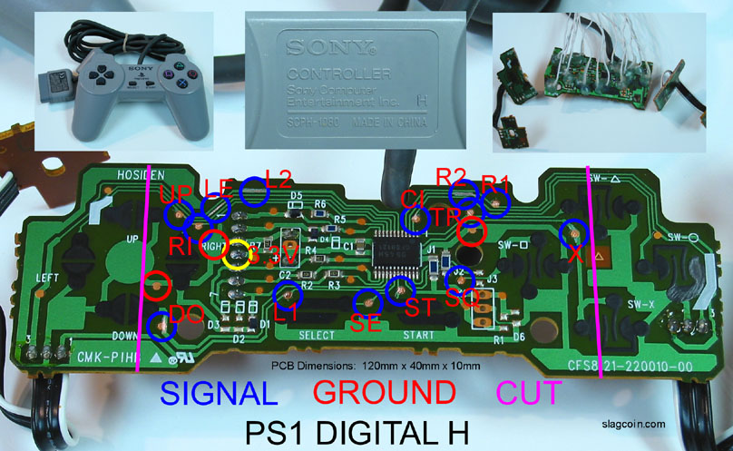
Here’s my understanding of how to do it. Please correct me if im wrong i dont know too much about this kind of thing. I would find a common ground ps2 circuit board. Scratch off the black material off of all the button contacts. Solder 1 signal wire to each contact. Put each signal wire in each quick disconnect on the barrier strip. The point that confuses me is this: What would i do with grounds? My understanding is You wire one ground wire on one of the contacts, and wire that to the TE circuit board. But that doesn’t make much sense to me. Is that right? Also, what would with a stock ps2 controller (non common ground to my knowledge)?.

Please leave any information/links/tips you can. Thanks.

EDIT: Also note: If i ever do end up doing this it will be quite a while later im not going to go fuck around with my new TE just yet. This is mainly for knowledge purposes.

What you said is basically it. You wire the circit board and make sure common ground are not crossed with signal.

If you’re only gonna do PS2 and PS3, it might not be a bad idea to just completely replace the PS3 pcb with a PS2 one, and buy a good adapter. You’d lose your home button, though.

But if you do want to do a dual mod, everything in this thread is still applicable:
2 PCB’s in one stick - Possible?

You’ll need a common ground PSone or PS2 pad - you can peruse this thread:
The “padhacking” thread

You also need to connect the +3.3V of PlayStation 2 to the +5V of PlayStation 3.

I thought PS2 pads ran fine under 5V?

Yes but you do only need one ps2 ground wire right? no daisy-chaining, or multiple wires?

Dual Mods require the Ground and VCC of both PCB to be connected.
No matter what.

Sorry for the complete noob comment. But what exactly does it mean to connect the ground and the VCC?

You already typed the Ground part in your First Post.
And I typed about the VCC part in my First Post in this Thread.

So i connect the pcbs with 2 wires? 1 for ground 1 for vcc?

more than just two, connect all inputs as well

And connect all the Signals of PlayStation 2 to Signals of PlayStation 3.
I read that you are handling that part with the Terminal Strip of TE?

Or, for PS3/PS2 I think a cthulu would be another way to go.

What do you mean im fairly sure you dont connect the two pcbs with inputs lol.

I wanted to do that but id rather go down the rough road and use a old broken controller than blow 35 bucks on a new pcb. Only problem being stock ps2 controllers are non common ground afaik

I don’t get what people mean by connect signals. if you mean put the ps2 signals in the qds with ps3 yah i get that much.

Signal is the side on pads that aren’t ground. Look at a diagram:

See? Signal and ground. Connect the same signals to each other.

Also, your best bet would be a digital PS1 pad, because they are common ground, unlike the DualShock 2, which is not.

I know it isn’t the most accurate drawing in the world, and its messy as shit, but if anyone can actually read it, can someone tell me how accurate this picture is?

You do.

Yes.

So you are not using Terminal Strip of TE I see.

i know what a signal wire was but i didnt get what they meant by connect them.