Hi,
when building arcade sticks common ground game pads are used for several reasons.
One reason using common ground pads is to connect common ground joysticks like seimitsu LS32-01 and Sanwa JLF sticks. These use common ground pcb 5 pin interfaces.
The dual PCB Mod needs also common ground xbox360 pads.
Also UPCB needs xbox360 common ground pads for piggyback.
Unfortunately there exists no more common ground pads in europe. This is sad but the truth.
I’ve found a solution to make out of non common ground pads common ground ones. I soldiered a prototype on breadboard. The solution is cheap and needs only few parts. Per signal you need one optocoppler and one resistor, thats all.

Here’s the padhack connected to the optocopplers on the bread board. Every pad has two wires to the optocoppler ICs. Pad used is Big Ben xbox360 game pad.

Close-up: The thick wires goes to a seimitsu LS32-01 Stick which is common ground.

And done. This mod works fine 
This is of course not the only way to find a solution for the common ground problem. One solution seems to be to fly to USA and get a common ground pad at gamestop or wal market. Another is to desoldier the GND-Pins of the microswitches.
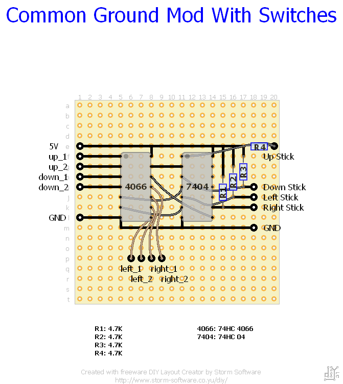
Toodles has made good experiences with 7404 hex inverters and 4066N analog switches.
Hope you like the mod.
nice work bencao74
btw I got a question
as you stated on hardedge
Isn’t Pin4 should be Gamepad’s GND for down direction.
because when I looked at 4N27 diagram, I found that Pin 4 is the emitor, Pin5 is collector and Pin6 is Basis
and this is using NPN transistor which means current from collector will flow to emitor if the transistor is in open state.
http://img264.imageshack.us/img264/1931/4n27.jpg
Don’t get an open collector Optocoupler, instead get a logic gate one, that way you don’t need a pull up resistor.
http://www.fairchildsemi.com/ds/FO/FOD2200.pdf
Just tie pin 6 to pin 5 to have the tri-state output always enabled. You could probably get enough free samples from Fairchild to do this whole project.
Hi,
@demonrush: Of vourse you’re correct!!
Here’s is the correct pin mapping
Pin1 -> resistor 1k Ohm -> 5V USB
Pin 2 -> Signal Arcade Stick, i.E. Direction Down
Pin3 -> Not Connected
Pin4 -> GND line from gamepad for direction down
Pin 5 -> Signal line from gamepad for direction down
Pin 6 -> Not Connected
@SiegeX1
Thanks for the hint! This IC makes the solution approach just more comfortable 
@SiegeX1: Do you know an IC with several FOD2200’s integrated?

This common ground mod are uses in arcade stick building for several reasons:
- keep the wiring easy (daisy chain for ground)
- dual PCB mod
- using the standard 5 pin connectors for sticks like sanwa jlf and seimitsu LS32-02
- connecting vintage joysticks like competition pro for sensible soccer

This is just another approach comparing to the optocoppler approach. Optocoppler a little bit more expensive. Therefore wiring is here mor complex and more parts are used.
Layout Description:
Joystick in general have the states disconnected (undefined) and active low. To define a active high for the inverter pull-up resistors (R1 - R4) are used when stick is disconnected.
When joystick is moved to one direction, signal is active low. Inverter changes it to active high. Active High is needed because 4066 switches only on Active High. The output pins are enabled and activate corresponding button on the xbox360 gamepad.
I’ve forget that this solution was proposed by Toodles in several threads, especially the pad hacking thread.
would this work for the buttons as well?
-joe
of course. You can put the complete pad to common ground.
Hi bencao74
I’m new to the stickbuilding business, and have some questions regarding the PC 817x mod
I have an old wireless org. MS 360 pad with non common ground.
Do you connect the 5V usb to the solder point on the controller? and what about the common ground, is that connected to a ground on the PCB, and then connected from the pcb to the jlf wiring harness?
I hope my questions is inderstandable.
best regards
Christianmp
Never tried this mod on a wireless one. Problem is that the wireless don’t have 5V. only 2.4 or 2.7V (not sure here).
Havin a wired one you can use 5V USB and common ground is GND USB.
Hope this helps.
I’m gonna give it a shot.
AFAIK the wireless (taken from slagcoins examples) has 3,3V
If all fails, I’ll have to cut the trace on the JLF and connect each sig/ground to each button.
I’ll return when the jobs done.
Hi,
use 220 to 330 ohm instead of 1k ohm and it will do fine for low power ps.
Bye,
Jochen
Here’s is the common ground mod applied to wireless xbox360 pad. Adjust resistors to 220ohm.
So no cutting traces or similar curious actions are needed.

Higher resolution
hello,
i’m about to start my first joystick and i was wondering if any of these would work as the optocoupler:
I’m guessing the ‘Hi-Sensitivity Opto’ will be fine?
thanks in advance,
>Marcus
edit: actually this ‘low-current optocoupler’ would work, correct… ?
re-edit: ignore the low-current one, it costs more 
Is this common line or common ground.
I can see the black wire from the pcb +v goes to the joystick harness with the pcb ground going to the resistors soldered to the opto.
Also u can put an appropriate resistor on the signal line going to the joystick (black wire) instead of using 4 resistors on the opto side.
hmm, yes of course!! Thanks man! Reducing this easy layout to just 2 pieces. 
Thanks bencao… no some one please give me some light and tell me where i can find optocopplers on internet :S


