Just watched the video and that is insane!! Nice work guys custom sticks are advancing to new heights every time I log in it seems =D
Now all we need is a quick disconnect wiring harness for easy plug and play swappable top panels. I always thought it would be cool to be able to swap out your whole top panel (Stick, buttons, art ect) with a different button layout by just removing the screws and 1 plug like a mini Jamma.
My idea was to make it with .110 QDs on one end and some sort of 20 pin plug system on the other. I’m sure somebody out there can make this happen or is secretly working on this right now. I just don’t have the time to fully commit to doing this or I’d be all over it.
This was my ghetto attempt, not exactly a “quick” disconnect but… lol
I meant a one-sided ribbon cable, and the other side going out to straight wires, which could be attached to the top panel, and thus removed with the top panel from the sparkplug, then pop on the new panel as you see fit.
Been a fan of your joystick work… I’ve been thinking about the same thing… some sort of quick disconnect between top and bottom panel… personally i hate all the extra ground wires from each button… it seems so unnecessary, when you can daisy chain grounds… but anyways, i was actually going to make something for my own stick since im always removing the top panel and fiddling with it…
i really hate quick disconnects… the headers off the 360 TE pcb are standard JST headers too… i’m still thinking about the best way to do it… dunno how many people would be interested in such a thing though…
Hey man I’m a big fan of your work too! If anyone can make this happen it’s you =D
I’d like to think lots of people would be potentially interested especially with the release of the new MK panels plus all the LL Custom Panels and not to mention my own case the VAS-TE a Brushed Stainless Steel TE replacement case.
The idea is that someone could connect their TE panel’s directly to the quick change adapter then swap them out with just one plug and never void their warranty. That parts not that important but some people might appreciate it
PM me if you want to bounce some ideas around I’d be glad to put in my input if think it would help?
Since it’s been awhile since anyone’s asked, has anyone got a chance to see how arceyes either 1.0 or 2.0 fit in Rollie buttons?
As far as I can tell, the three factors that would come into play are the outer circumference, inner hole circumference, and height.
The Rollie buttons themselves seem a little larger in circumference than the PS-14-KNs but I don’t know how the middle post area compares in size. I do know that the “UILA RGB 5VDC LED Lamp” board sold from the same site is a tad too big in circumference to fit in the PS-14-KN buttons. Also, with the new pins on the 2.0’s I don’t know how the height would be affected. Spenzalli, I know you have a good amount of experience with arceyes, any thoughts?
This is what I did. Anything but solderless though, that breadboard took me all day.
In retrospect putting it all on the bottom was a bad call, I have to take both panels off to do anything now. If it’s on top you can daisy-chain your grounds too.
You could get a PC board made and machine-populated, but I don’t know how you’d go about larger scale production of the cabling. I think there are places that will do it, but I’m not sure how automated it is so it may be pricey. And making cables yourself is really tedious.
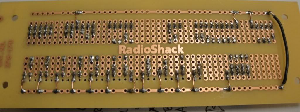
Well then: full resolution
The button wiring is a little messed up because what I had on-hand was either too small for the quick disconnects or too large for the c-grid connectors. Also, the locking c-grid connectors are classy but 3x as expensive as a simpler choice, but I knew I had access to the right crimper for them.
Oh, and in case you were curious about the business side: the breadboard. (Before rework to fix accidentally wiring the guide and start buttons together.)
1.0 will fit with no problem. You will need to figure out how to attach the arc eye to the button, as the switches are different (sanea type switch as opposed to the seimitsu switch, which the arc eye is designed to friction fit onto) but spacewise no problem. As for 2.0, can’t say just yet. They might, but I’d need one to test on (or purp would need a rollie button to test on)
I swear I thought I read the 2.0s wouldn’t fit. The wild rumors I read these days, so when someone makes them fit I will eat my humble pie and even if it taste like sweaty gym socks and farts I’ll tell everyone I know it was delicious. /fail
Arceye2 will be a little taller on the LED side due to the header pins, but if this is a problem i can special cut the pins down a little on the top to make the profile the same height as arceye1.
Arceye1 has cuts on the top and bottom to specifically fit snap in semitsus, so if the un-cut sides has clearance all the way around, arceye2 shouldnt be a problem.
And lastly, if the pins will clear the switch, then you’re good. The way you can check this is on a semitsu button, the pins will hang just off the side of the widest part of the switch housing.
Of course it would greatly help if someone could take side by side pics of the interior, and bottom of rollies together with semitsu screw ins. I don’t even know what these buttons look like…


