Is there a good diagram to show how to use a toggle switch for moving between ps3/xbox stick?
http://www.colehersee.com/04resource/images/DPDT2.gif
please correct me if i’m wrong.
load 1=green wire from ps3 usb
load 2=white wire from ps3 usb
load 3=green wire from xbox usb
load 4=white wire from xbox usb
it’s not labeled, but the pins between 1&3 is the green output usb and between 2&4 would be the white wire.
any ideas?
If anybody could help as I’m stumped… I’ve checked about 500 more times and don’t see anything wrong…
the only thing different than what I’ve seen before is that I have my stick grounded before the buttons in the daisy chain instead of after the buttons on most diagrams, but I fail to see how this matters…
If you need any more details, let me know and I’ll post them up…
I’m stumped… :crybaby:
how about posting up pics? which 360 controller did you use?
I’ll get some pics although it’s next to impossible to get everything clearly… the hrap is a bit cramped…
it’s a Madcatz retro pad…
definately sounds like something is not wired correctly. shouldn’t your buttons function as LB/L1, LT/L2, RB/R1, & RT/R2?
according to everything I’ve ever read… 
pics up soon…
Deep Breath
First, hello. I’ve lurked around this forum for some time, but predictably only SFIV (and my subsequent purchase of a PS3 TE stick) prompted me to make this reply. Please, don’t lynch the newbie. Thanks to everyone in this thread so far, especially the post linked above, it’s made things a lot clearer.
I’m currently in the process of sourcing parts of my PS3/X360 TE Dual Mod, and I wanted to query something about the above diagram. In short, why is the DPDT switch connected to D+/D-, instead of simply just powering the appropriate PCB, and avoiding any attendant nastiness of having both powered? There seems to be a lot of commentary around the issue, but I’ve not seen anything that clearly explains it. I was considering remedying it in my design as a potential design error, but wanted to see if there was already a trail of failed efforts that met some gotcha I wasn’t aware of.
Thanks in advance for any help that can be offered. Oh… and ‘Hi’. 
the reason why dpdt switch is connect to signal (D-D+) instead of switching power are follow
- using 1 usb cable instead of 2
- since both pcb is connect, it will pull weird input signal if 1 pcb or the other is not power on
simply put, with both controller’s D+/D- connected together causes communication problems through usb.
the reason both boards are powered is because the signal lines from both boards are connected together. If only one board is powered, then the button’s signal line from one controller gets pulled low from the other connected button (and would be registered as a button being held down). If you really needed to have only one board powered at a time, you could add a diode to each button, but for the purpose of a dual wired mod, doing so would be wasteful and stupid.
Here are pics… like I said, no joystick wires are hooked up to the buttons, but 3 of my directions come out of the buttons…
First is a wiring diagram… kinda crazy, but you’ll see the photos and this is tame compared to the real thing…
http://farm3.static.flickr.com/2462/3654744433_a5927629c6_o.jpg
That link’s the full size… The little green box on the right is the usb strip on the front of the board…

Various photos…


Sorry for the Mess!
Ok so here is what I did to my stick. Please forgive my lack of knowlege and crude terminoligy, like it says in the post I know nothing about this stuff. Ive been doing it for 2 1/2 days now. hehe

Its a bit messy but its my first time ever doing anything like this. I spent 4 hours the night before takin’ apart my old ps1 controllers and practiced soldering on those. I just used guides and pictures from here to wire the 360 pcb.
Now I dont know if the way I did it is right but it works somewhat. I didnt remove anything that was originaly in the stick. I left it all there and I just cliped the quick disconnects, then I striped the wire and twisted it together with the wire from the 360 pcb and put a new quick disconnect. I did that to all the buttons and the grounds.
My problem is, I dunno how to get the ps2/xbox part to work. I sorta figured it out I think. I read around and I guess I just have to wire the power supply from the sfa pcb to the 360 pcb. But I dont want to remove the pcb thats in there and I dont want to cut all the wires up. I dont have a multi meter to find out where the power supply is in either of the pcb. But I think the sfa one is marked. But once again im not for sure.
So for now I just have to disconnect the strip thing on the top and right side of the board and the 360 pcb works fine. So if where its marked is the wire I need to run between the two pcbs, would it just be ok to expose some of that wire and twist another wire to it? You know, then I can run that wire to the 360 pcb.
And I need to know where to solder the wire on the 360 pcb. Is it the little nod (that what its called?) that has USB marked under it? Its directly down from where I have the start button wired.
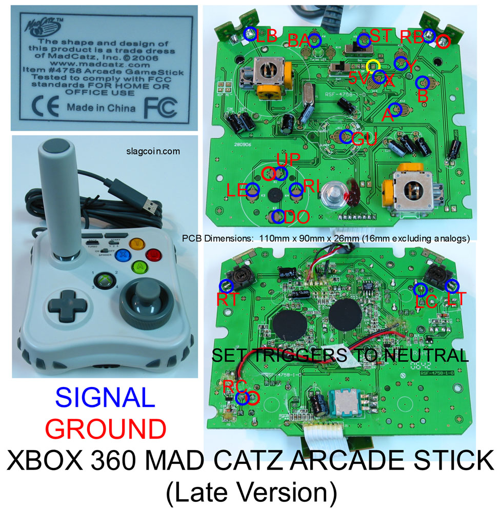
On this diagram it shows a black and red wire on the back of the pcb…
Mine does not have this… is this something I need to add? If so, I can’t tell exactly where i’d add it…
also, it says set triggers to neutral… is this referring to the resistors, or is there something else to be done?
danz-
To set triggers to neutral it just means make sure they are both unactivated and make sure nothing will rub on them to activate them.
Not sure about the red and black wire on the back of that pcb, havent done one of those yet, i believe there used to be a diagram for an early version if im not mistaken.
how do you make sure they are un-activated?.. I pulled off the entire trigger assembly as many have posted pics of before…
thats it, just make sure you dont lay the pcb triggers down. Or lay another pcb or terminal strip against it either. In a hrap you should have plenty of room.
Looks like a jungle of wires, lol, gonna be fun going through them all.
I think I’m close… I have the joystick hitting all directions…
I think the bumpers might by default go left and right on the xbox dashboard… so this just leaves the triggers… but like I said, there are no triggers there… they were removed… if you look it’s just the pcb solder points on the back with a 10k resistor…
as I understand the resistor can be installed either direction… if I’m wrong, somebody let me know…
then I need to clean stuff up and fix some wiring so the ps3 portion will work…
AJ, I might come over soon to test since my PS3 is dead…
cool bro, hit me up.
#Edit- tonight wont be good, but any other day
it’ll most likely be next week…
#1 goal is to get it working on the Xbox since that’s the console I play it on now…
okay… I have everything working…
…almost
the Y button won’t work… my friend soldered it, but I think he fried the solder point…
i tried to solder to the corresponding point on the back of the board, but still no dice…
Any other place I can solder or some other solution? If not, I’m hosed and hours of work are down the drain… 
I’ll post pics tomorrow…