2 PCB's in one stick - Possible?

from what I have read on the forum, (did not personally try it yet)

you need to hook up the power source to both PCBs

both PCB will be on when you plug in the USB cable but you will be choosing which PCB’s signal you want to send to the console/computer by using the DPDT switch

Heres a bright Idea I had that I’m pretty sure most of the people on the forum are going to hate.

I’m getting a 360 within the next month, but I play on older consoles and have a Wii too. Hence I need something with multiconsole support. Sadly, the wonderful :arazz: people at Microsoft have implemented security protocols in their controllers which force me to Dual PCB my stick.

So PCB 1 is obvious, Mad Catz, probably arcade stick. That will get me 360 support. PCB 2 is where I am entering the controversial territory, mostly because I don’t have much of a choice to get GC and PS2 support. I’m thinking of using one of the newer X-Arcade PCBs. From what I understand the newer ones have not been lagging. And it wold give me dang near full console support. Anyone know if that setup would be possible?

okay. i read through the whole thread. just wanna be sure… if i wanna hook up a DC and PSX controller…

just simply like the common grounds on both pads, and the 5v and the 3.3v together…then im good to go? then just wire everything up to a terminal strip and wire things up as if i was doing a single pcb? thanks.

why not use a sony digital pad and use and adapter or get one of toodles UPCB’s.

… you still need a DPDT switch connecting to the signal output of both PCB’s so that you can chose which signal you want to send through the cable, instead of signals from both PCB and confuse the hell out of your console

what happens if we’re willing to just have both cables stick out of the stick? I don’t want anything weird, just 2 pcb’s and 2 wires

As long as you don’t plug in both at the same time you’re good. If you do have both you run the risk of causing damage to the pad or console.

thanks for the help, time for me to just get me one of those cthulu boards then

did that with a DC and PSX pad, worked on my ps2, but fried my controller port on DC… anyone have any idea what’s going on? thanks.

DC fuses go if there is too much current drawn. Sounds like you have a short somewhere. Use your multimeter and test the resistance between the ground line and the power lines.

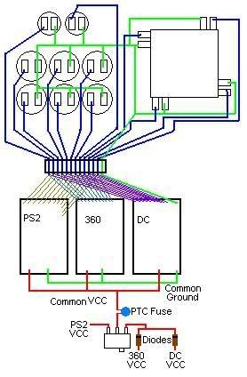
After reading the thread, I figured I’d try my hand at making a simple 3 PCB schematic.
Is there anything wrong with this?

(I have an Agetec Stick I’d like to mod for 3 systems, and I figured I’d put this up for review before I fry it.)
If there’s nothing wrong with it, I hope this helps anyone who wants to try a similar setup.

That looks really good. The switch in the lower right though needs a little tweaking though. The ‘common VCC’ line should go to the middle leg of the switch, with your 5v sources on one side leg, and the PSX on the other side leg. You might also want to move the PTC fuse to the common VCC leg so it’ll protect no matter which console is in use; it doesn’t drop the voltage like the diodes do (well, not enough to matter at any rate) so its safe to use on a PSX.

I can see exactly what you’re meaning, using the blue colored lines to show a bus of all of the signal lines; a little explanation to go with the picture would probably help, before some folks ask why all of the buttons are connected together.

I looks like you got the idea for the wiring down. Now I can’t wait to see you cram all of that into an Agetec. :slight_smile:

I’d like to see more details on the idiot proof switch too, diode sizes, fuse size etc.

Michael

Yeah, I got a little lazy on the individual button lines, but you get the idea. I had no idea which leg was what on the switch, so I just laid them out like I did. (I’ve never used one before.)
@Kaytrim: I have no idea what sizes of diodes or fuses to use; I simply drew the picture to see if I’ve got the right idea as far as what to hook up and where. Toodles may be able to give suggestions.

I’m looking into building a new housing, as the Agetec may not fit all of that at once. If I pulled off fitting it all in there, it would not be pretty to look at. (on the inside, anyway.) There’s a rat’s nest in there as it is after modding it with a PS2 PCB, and I don’t even have a common ground 360 board yet.

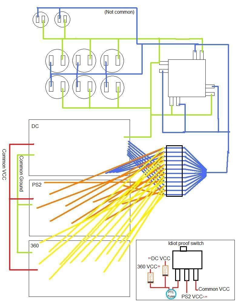
Edit: Here’s a quickie MSPaint of the revised setup:

Anything in particular you’re looking for? The switch is just a regular SPDT switch; it selects whether the power going to all of the boards is coming from one of the 5v cords (DC, Xbox360) or 3.3v cord (PSX).

My write-up on diodes: Diodes do two things. #1 They allow current to only go through it one way. So, if its wired like shown in that drawing, current can come FROM either one of the two 5v consoles, but no power can go TO either console. This is to protect the consoles so we can draw current from them without accidently force feeding current to them, creating short circuits, blowing fuses, and all manner of nasty things. Draw what we need from one or both, without allowing current from one console to go to the other. #2 Diodes drop the voltage across them. Most cheap diodes will drop about 0.6 volts, so the voltage available from either 5v system will actually be about 4.4v once it gets to the other side of the diode. It’s kind of like a one-way turnstile at a stadium or subway entrace; people have to slow down to go through them, but they sure as hell can’t go through them backwards. That’s also why diodes have markings on one end, because if you put them in backwards, then none of the current we need will be allowed to go through, but the backwards current we want to avoid will be allowed through, so doublecheck your orientations.

The reason he has diodes on the two 5v system and not on the PSX cable is because of that voltage drop. If you drop the 3.3v by 0.6v, you’ve cut the available voltage by 1/3rd, and we quickly get into areas where the possibility of the PSX pad not working is something to worry about. On the 5v systems, we only cut the voltage by about 10%, which is safe to rely on. So, he used a toggle switch.

All of that corner is just to help protect the consoles (and the stick I suppose) against problems if it is plugged into more than one console at a time. If he plugs in the DC and Xbox, the pcb’s will be allows to draw the current they need from either or both systems without worry because the diodes won’t allow current to feed back into the console where it will cause problems. If it’s plugged into the PSX as well, no one cares because the slide switch has the power line disconnected from anything; no power going either direction. If the slide is in the PSX side, then all of the power is comng from the PSX, and there is no way for the pcb’s or PSX to pull power from the 5v systems since they are disconnected at the switch. The two 5v system’s power lines are connected together, but with the diodes there, no current can move either way. Everything’s safe.

Just about any diode can work for this protection; even cheap N4148’s you can find at any Radio Shack. Just look for the cheapest pack of diode’s and you’ll have ones that work. If you don’t mind spending the money on them, you can also try to hunt down diodes with obscenely low voltage drop. The voltage drop (denoted as Vf or ‘forward voltage’ in the datasheets) is how far, umm, the voltage drops across the diode. If you hunt around for one with a very low voltage drop, you can have all three consoles’ power lines connected, using the spendy low voltage drop one on the PSX cable, and whatever diode you like on the 5v systems. Here’s one I found:
http://search.digikey.com/scripts/DkSearch/dksus.dll?Detail?name=VS95SQ015-ND
It’s spendy, but the voltage drop across is less than 0.1 volt. for low current stuff like this.

The PTC fuse is a self resetting fuse, like a circuit breaker that resets itself. If too much current goes through it, it stops the current, hopefully soon enough so your console doesn’t fry. Here’s one that I use for the UPCB:
http://search.digikey.com/scripts/DkSearch/dksus.dll?Detail?name=RXEF040-ND

Zonekeeper: new image looks nice!
darn it. can’t find my multimeter, :mad:

anyways, tested the pcb’s separately on both system and worked fine, but as soon as i link the common ground;5v on DC and 3.3v on psx together. everything works on my ps2, but fries the DC again, good thing i know how to fix the DC…lol.

a switch is NOT required right, i read through the whole forum, too much info at once, got me a little confused. lol.

can someone explain how this works out physically?

im working with a cthulu/madcatz/hrap2sa so i’d figure i only need a diode between the 360 and hrap2 pcb.

http://img241.imageshack.us/my.php?image=helpqg0.png

any problems with this diagram

There’s a post by me two posts above yours with a pretty complete writeup on diodes. If you have any questions, please ask.

Oh god yeah. Grounds aren’t connected to all pads. Toggle switch for selecting USB system is toggling D+ and Ground when it should be D+ and D-. 3.3v line has two diodes in opposite directions, meaning no current can flow either direction, etc. Schematics in this thread are much better. I don’t mean to be insulting if you did that, but scrap that one and start over.

oh its just a quick crude drawing i did at work to help with some questions and help myself visualize it
so insult it all you want

…oh man this finally makes sense


but would it be the same if its a 5v pad and a 3.3v pad
wouldnt the ps2 pad not get enough power

Thanks for the further infos on the diodes+fuse use.
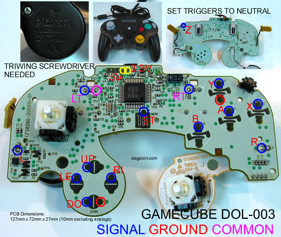
I wanna do a triple pcb mod, HrapEx shell, madcatz arcade pcb (360) (5V), Mayflash pcb (PS1-2-3) (5V) and DOL-003 pcb (GC).

question about the DOL-003 pcb>

what’s the deal with LT, RT, L, R ? ( does it mean I can just use L and R points as if they were regular digital buttons? and leave LT, RT like that ?) what about the “common” next to LT ? should I wire it up with the ground wire ?
what am I supposed to do with the 5V and 3.3V ? which one should I wire to the other pcbs (same question goes for Mayflash pcb as it has a ps1 3.3V connector and a usb 5V connector on the pcb)

thanks in advance ! :slight_smile: